00194103-01.pdf - 第96页
3 Technical data User Manual S IPLACE F5 H M 3.11 PCB single conveyor Software Vers ion SR.408.xx 03/ 2006 US Edition 96 3.1 1 PCB single conveyor 3.1 1.1 S tructure The plac ement sy stem is supplie d with a s ingle co …

User Manual SIPLACE F5 HM 3 Technical data
Software Version SR.408.xx 03/2006 US Edition 3.10 Vision modules
95
3.10.2 Technical data - Standard component vision module on the
6-segment C&P head
3
3
3.10.3 Technical data - Fine-pitch vision module
3.10.4 Technical data - PCB vision module
Component dimensions 1.6 x 0.8 mm² up to 32 x 32 mm²
Component range 0603 to 32x32mm²
PLCC, SO, QFP, TSDP, SOT, MELF, CHIP, IC BGA
Min. lead pitch 0.5 mm
Field of vision 24 x 24 mm²
Method of illumination Front lighting (three levels, programmable as required)
Max. component size 32 x 32 mm² (single measuremen)
55 x 55 mm² (multiple measurement)
(larger components possible on request)
Component range PLCC, LCCC, QFP, SO, BGA, flip-chip,
components with connectors up to 55 x 55 mm²
(J leads and gull-wings, balls, bumps)
Min. lead pitch 0.4 mm
Field of vision 38 x 38 mm²
Method of illumination Front lighting (three levels, programmable as required)
Fiducials up to 3 per placement program
Local fiducials up to 2 per PCB (may be of different types)
Library size up to 255 fiducial types - system fiducials ≥ 249
Image analysis Correlation principle based on grayscale values
Method of illumination Front-lighting
Detection time per fiducial/bad fidu-
cial
0.4 s
Field of vision 5.7 x 5.7 mm²
3 Technical data User Manual SIPLACE F5 HM
3.11 PCB single conveyor Software Version SR.408.xx 03/2006 US Edition
96
3.11 PCB single conveyor
3.11.1 Structure
The placement system is supplied with a single conveyor as standard. A dual conveyor is avail-
able as an option. The left or the right side of the PCB conveyor can be used as the stationary
side, as required. 3
3
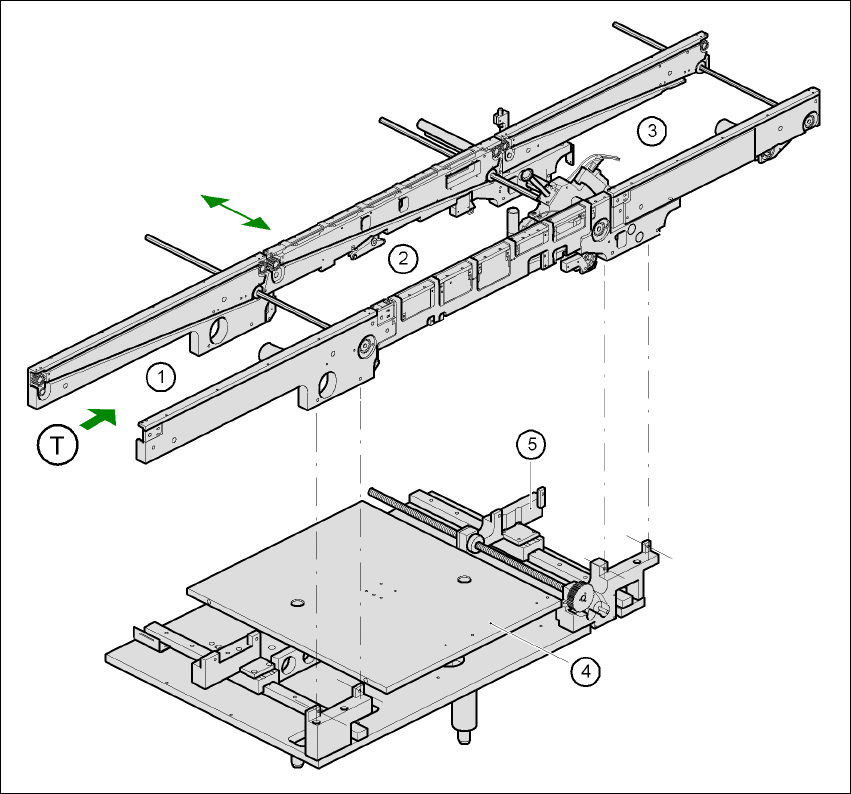
Fig. 3.11 - 1 Structure of the PCB single conveyor
(1) Input conveyor (2) Center conveyor
(3) Output conveyor (4) Lifting table
(5) Width adjustment T Direction of PCB transport 3

User Manual SIPLACE F5 HM 3 Technical data
Software Version SR.408.xx 03/2006 US Edition 3.11 PCB single conveyor
97
The conveyor belts are driven by DC motors. The lifting table in the center conveyor area clamps
the PCBs. The width of the PCB conveyor can be adjusted either via the menu or the SIPLACE
Pro computer. 3
3.11.2 Technical data - single conveyor
3
3
PCB format 50 x 50 mm² up to 460 x 460 mm²
2" x 2" up to 18" x 18"
Optional: up to 508 x 460 mm²
up to 20" x 18"
PCB thickness 0.5 up to 4.5 mm
Max. PCB warpage up: 4.5 mm - PCB thickness
down: 0.5 mm + PCB thickness
Clearance on PCB underside 25 mm (standard), 40 mm (option)
PCB transport height 830 mm ± 15 mm (standard)
900 mm ± 15 mm (optional)
930 mm ± 15 mm (optional)
950 mm ± 15 mm (SMEMA: optional)
Fixed conveyor side Right (standard), left (optional)
Type of interface Siemens (standard), (SMEMA, option)
Component-free PCB handling
edge
3 mm
PCB changeover time 2.5 s