00197279-03_SM_Glue-Feeder_EN.pdf - 第19页
Replacing Spare Parts 3.6.2 Fitting the Cartridge Adapter O-ring O-Ring for Cartridge Adapter Service Manual SIPLACE Glue Feeder 19 3.6.2 3 . 6 . 2 F it t in g t h e C a r t r id g e A d a p t e r O - r in g Fitting the …
Replacing Spare Parts
O-Ring for Cartridge Adapter 3.6.1 Removing the Cartridge Adapter O-Ring
18 Service Manual SIPLACE Glue Feeder
3.6
3.6 O-Ring for Cartridge Adapter
O-Ring for Cartridge Adapter
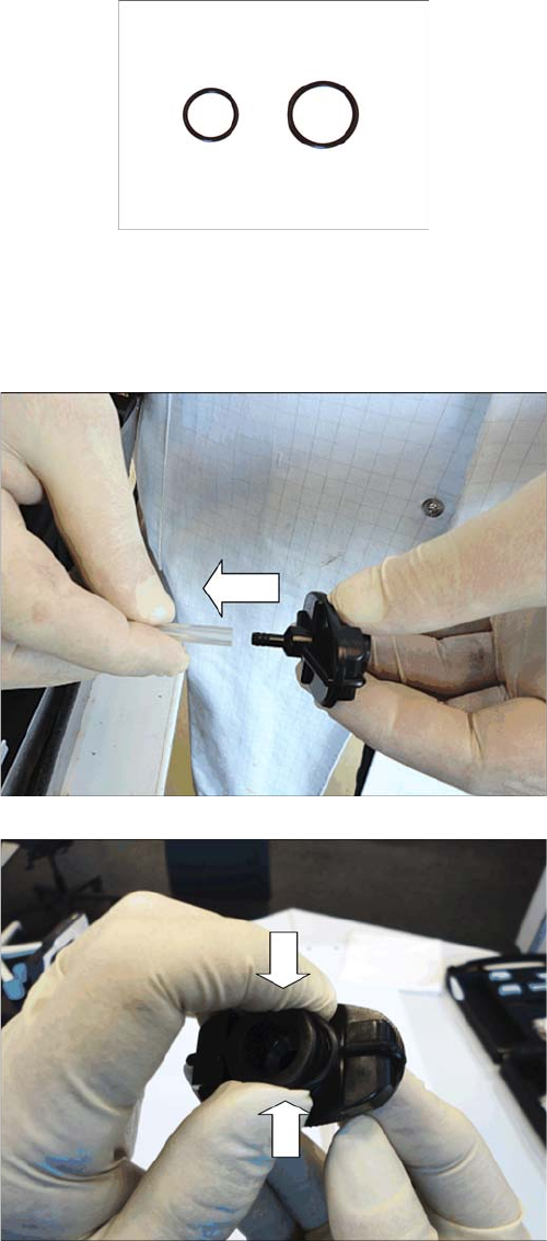
Required spare parts
O-ring for Optimum adapter 10ccm, item no. 03094186-xx
O-ring for Optimum adapter 30ccm, item no. 03094185-xx
3.6.1
3.6.1 Removing the Cartridge Adapter O-Ring
Removing the Cartridge Adapter O-Ring
► Remove the cartridge adapter from the cartridge (see
"3.5.1 Removing the Cartridge Adapter" [ ➙ 15]).
► Pull the hose off the cartridge adapter.
► Press the O-ring on the cartridge adapter firmly to
-
gether.
The O-ring will form a tiny loop at the side.
Replacing Spare Parts
3.6.2 Fitting the Cartridge Adapter O-ring O-Ring for Cartridge Adapter
Service Manual SIPLACE Glue Feeder 19
3.6.2
3.6.2 Fitting the Cartridge Adapter O-ring
Fitting the Cartridge Adapter O-ring
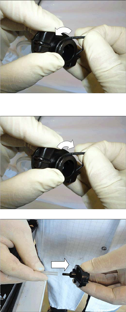
► Grip this tiny loop and pull the O-ring off the cartridge
adapter.
► As shown in the diagram, fit the O-ring on one side
onto the cartridge adapter and pull it over the rim.
Make sure that the O-ring is fitted evenly against the
surface all around.
► Fit the hose to the cartridge adapter.
► Fit the cartridge adapter into place (see "3.5.2 Fitting
the Cartridge Adapter" [ ➙ 16]).
Replacing Spare Parts
Left Side Cover 3.7.1 Removing the Left Side Cover
20 Service Manual SIPLACE Glue Feeder
3.7
3.7 Left Side Cover
Left Side Cover
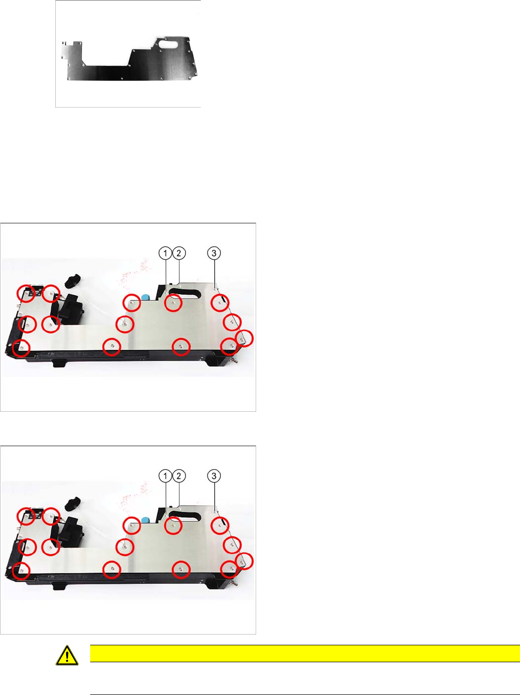
Required spare parts
Cover for glue feeder, left, item no. 03088710-xx
Required tools
▪ Phillips screwdriver
▪ TORX screwdriver size T8
3.7.1
3.7.1 Removing the Left Side Cover
Removing the Left Side Cover
3.7.2
3.7.2 Fitting the Left Side Cover
Fitting the Left Side Cover
► Carefully place the feeder module with the right-side
side down on a stable, level and clean surface.
► Loosen the screws marked in the diagram. The
screws 1, 2 and 3 are Torx screws, while all other
ones are Phillips screws.
► Carefully place the feeder module with the right-side
side down on a stable, level and clean surface.
► Loosen the screws marked in the diagram. The
screws 1, 2 and 3 are Torx screws, while all other
ones are Phillips screws.
CAUTION
Do not distort the screws
When you tighten the screws, make sure that these are NOT distorted.