00197279-03_SM_Glue-Feeder_EN.pdf - 第78页
Replacing Spare Parts Regulator Holder Assembly 3.19.2 Fitting the Regulator Holde r 78 Service Manual SIPLACE Glue Feeder 3.19.2 3 . 1 9 . 2 F it t in g t h e R e g u la t o r H o ld e r Fitting the Regulator Holder See…
Replacing Spare Parts
3.19.1 Removing the Regulator Holder Regulator Holder Assembly
Service Manual SIPLACE Glue Feeder 77
3.19
3.19 Regulator Holder Assembly
Regulator Holder Assembly
Required spare parts
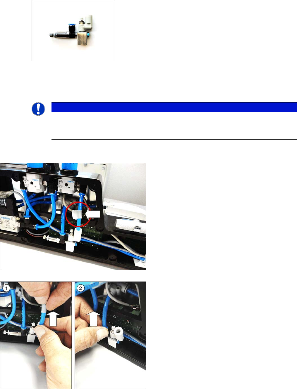
Regulator holder assembly, item no. 03097710-xx
Required tools
▪ Allen key size 2
3.19.1
3.19.1 Removing the Regulator Holder
Removing the Regulator Holder
NOTICE
Assembly instructions
The regulator holder is always replaced as a complete unit.
This regulator holder is preset at the factory and is supplied ready for use.
► Remove the right side cover (see "3.8.1 Removing
the Right Side Cover" [ ➙ 21])
► Mark the hose indicated in the diagram, with adhe
-
sive tape.
► Open the lock and pull the marked hose out of the
connection on the right-hand side. (1)
► Open the lock and pull the hose out of the connection
on the left side. (2)
Replacing Spare Parts
Regulator Holder Assembly 3.19.2 Fitting the Regulator Holder
78 Service Manual SIPLACE Glue Feeder
3.19.2
3.19.2 Fitting the Regulator Holder
Fitting the Regulator Holder
See also
3.8.2 Fitting the Right Side Cover [ ➙ 21]
► Carefully place the glue feeder down on its left side.
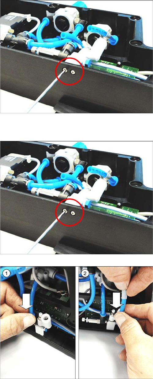
► Remove the two marked screws. Use a size 2 Allen
key for this.
► Remove the regulator holder.
► Carefully place the glue feeder down on its left side.
► Coat the tips of the two screws with LOCTITE 243.
► Use the two marked screws to fasten the regulator
holder. Take a size 2 Allen key for this.
► Insert the UNMARKED hose as far as possible into
the connection on the left side. (1)
► Insert the marked hose as far as possible into the
connection on the right-hand side. (2)
► Fasten the right side cover (see .
Replacing Spare Parts
3.20.1 Removing the Plug-in Fitting Plug-in Fitting
Service Manual SIPLACE Glue Feeder 79
3.20
3.20 Plug-in Fitting
Plug-in Fitting
Required spare parts
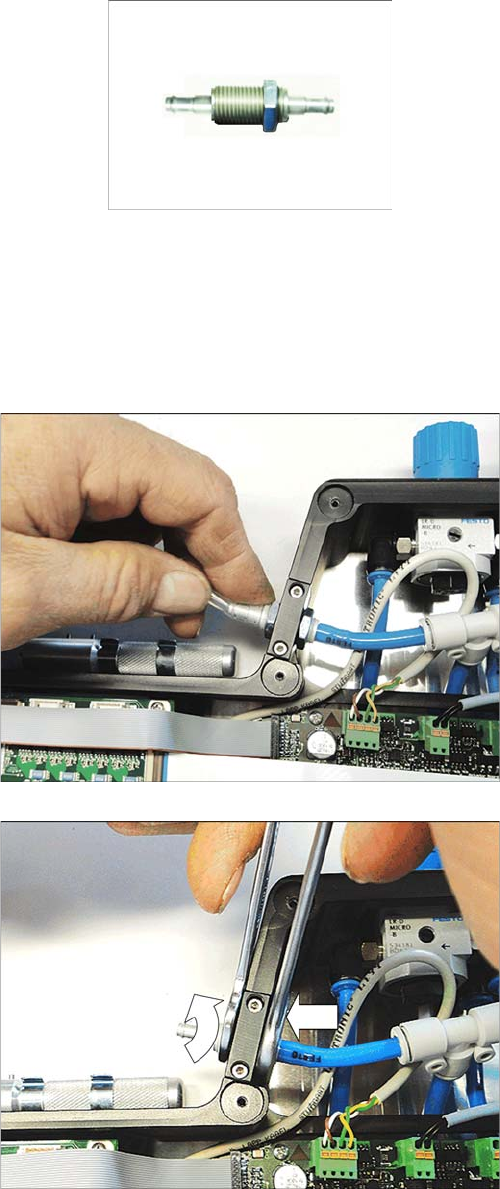
Plug-in fitting SCN-PK-4 SCN-PK-4, item no. 03095834- xx
Required tools
▪ 2x open-ended wrench, size 13
3.20.1
3.20.1 Removing the Plug-in Fitting
Removing the Plug-in Fitting
► Remove the left side cover (see "3.7.1 Removing the
Left Side Cover" [ ➙ 20].
► Disconnect the silicon hose leading to the cartridge
from its plug-in fitting.
► Remove the outer nut which fixes the plug-in fitting to
the frame. Use 2 size 13 fork wrenches for this.
Use one to hold the nut on the inside of the frame, so
that this nut does not turn, and the other one to re
-
move the outer nut.