00197279-03_SM_Glue-Feeder_EN.pdf - 第88页
Replacing Spare Parts EDIF Secondary Assembly 3.23.2 Fitting the EDIF 88 Service Manual SIPLACE Glue Feeder 3.23.2 3 . 2 3 . 2 F it t in g t h e E D I F Fitting the EDIF ► Check the compression springs for damage an d re…
Replacing Spare Parts
3.23.1 Removing the EDIF EDIF Secondary Assembly
Service Manual SIPLACE Glue Feeder 87
3.23
3.23 EDIF Secondary Assembly
EDIF Secondary Assembly
Required spare parts
EDIF secondary assembly. /X2x8, item no. 03065209-xx
Required tools
▪ Flat bladed (slotted) screwdriver
▪ Allen key size 2
3.23.1
3.23.1 Removing the EDIF
Removing the EDIF
► Place the feeder on a stable, level and clean surface.
► Remove the left side cover (see "3.7.1 Removing the
Left Side Cover" [ ➙ 20].
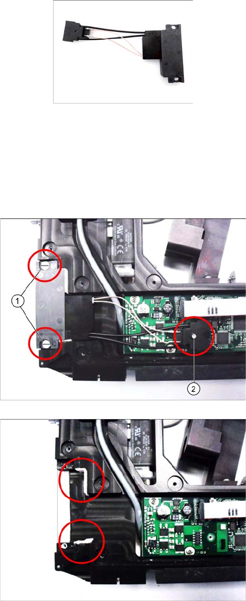
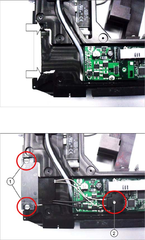
► Remove the two collar screws. (1) Use a slotted
screwdriver to help you.
► Remove the screw (2) which fastens the connector to
the board. Use a size 2 Allen key for this.
► Lift the connector carefully off the board and remove
the EDIF.
► Check that the EDIF foam sealing at the top and bot
-
tom is not damaged or worn and replace if required.
Replacing Spare Parts
EDIF Secondary Assembly 3.23.2 Fitting the EDIF
88 Service Manual SIPLACE Glue Feeder
3.23.2
3.23.2 Fitting the EDIF
Fitting the EDIF
► Check the compression springs for damage and re
-
place if necessary.
► Insert the EDIF and fasten into place with the two col
-
lar screws (1). Use a slotted screwdriver for this.
Make sure that the two compression springs point to
the front and are not distorted.
► Check whether the EDIF springs back to the front if
slight pressure is applied to it.
► If the EDIF does not spring back, loosen the collar
screws (1) and check or correct the position of the
two compression springs (see above).
► Place the connector on the main board, ensuring the
alignment pins engage in the holes.
► Carefully screw the connector to the board. (2) Use a
size 2 Allen key for this.
► Fasten the left side cover (see "3.7.2 Fitting the Left
Side Cover" [ ➙ 20].
Replacing Spare Parts
3.24.1 Removing the Handle Assembly Handle assembly
Service Manual SIPLACE Glue Feeder 89
3.24
3.24 Handle assembly
Handle assembly
Required spare parts
Handle with control panel V1 GlueFeeder, part no.: 03133349-01
(prefitted with flat ribbon cable)
Required tools
▪ Allen key, size 2.5
▪ TORX screwdriver size T8
▪ Open-ended wrench, size 24
3.24.1
3.24.1 Removing the Handle Assembly
Removing the Handle Assembly
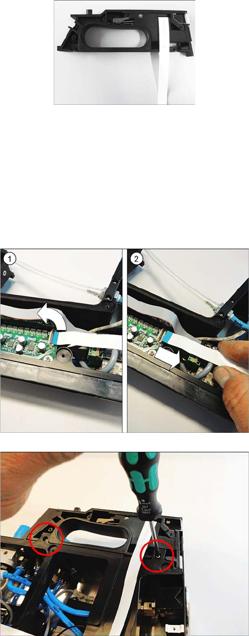
► Remove the left side cover (see "3.7.1 Removing the
Left Side Cover" [ ➙ 20].
► Carefully place the glue feeder down on its right side.
► Open the bar on the flat ribbon connection on the
control board. (1)
► Unplug the flat ribbon cable form the connection. (2)
► Remove the two marked Torx screws.