Printer 710_810 v8 Machine Control.pdf - 第12页
MACHI NE CONT ROL M36 MACH INE CO NTROL E NCLOS URE 7.12 Technical Reference Manual Chapter Issue 8 O ct 06 NextMove Interf ace Edge Connector The edge connector connect s the card to the backplane of the enclosur e. Pin…
MACHINE CONTROL
M36 MACHINE CONTROL ENCLOSURE
Chapter Issue 8 Oct 06 Technical Reference Manual 7.11
Inputs The table below details the 20 digital inputs:
NOTE
DIG IN 7 and 9 are not used on the RTC machine.
Outputs The table below details the 8 digital outputs:
Input Function Input Function
DIG IN 0 Spare DIG IN 10 Board at Left
DIG IN 1 Camera X Home
(linear drive machines only)
DIG IN 11 Board at Right
DIG IN 2 Camera Y Home
(linear drive machines only)
DIG IN 12 Jog Left
DIG IN 3 Front Squeegee Home/ProFlow
Contact Sensor
DIG IN 13 Jog Right
DIG IN 4 Rear Squeegee Home DIG IN 14 Power ‘ON’ Monitor
DIG IN 5 Moving Rail Home DIG IN 15 Cover Interlock
DIG IN 6 Rail Lifted - Left/Rail Lifted (RTC
machine)
DIG IN 16 Upline Ready
DIG IN 7 Rail Lifted - Right DIG IN 17 Downline Ready
DIG IN 8 Board at Stop DIG IN 18 Board Pass I/P
DIG IN 9 Board Stop Extended DIG IN 19 Spare
Output Function Output Function
DIG OUT 1 Trigger Image Capture DIG OUT 5 Send Upline
DIG OUT 2 Belt Motors Start-Stop/Inroad Transport
Belt Enable (RTC machine)
DIG OUT 6 Send Downline
DIG OUT 3 Belt Motors Direction/Outroad Transport
Belt Enable (RTC machine)
DIG OUT 7 Board Pass O/P
DIG OUT 4 Spare Error Out Software E Stop Power
MACHINE CONTROL
M36 MACHINE CONTROL ENCLOSURE
7.12 Technical Reference Manual Chapter Issue 8 Oct 06
NextMove Interface
Edge Connector
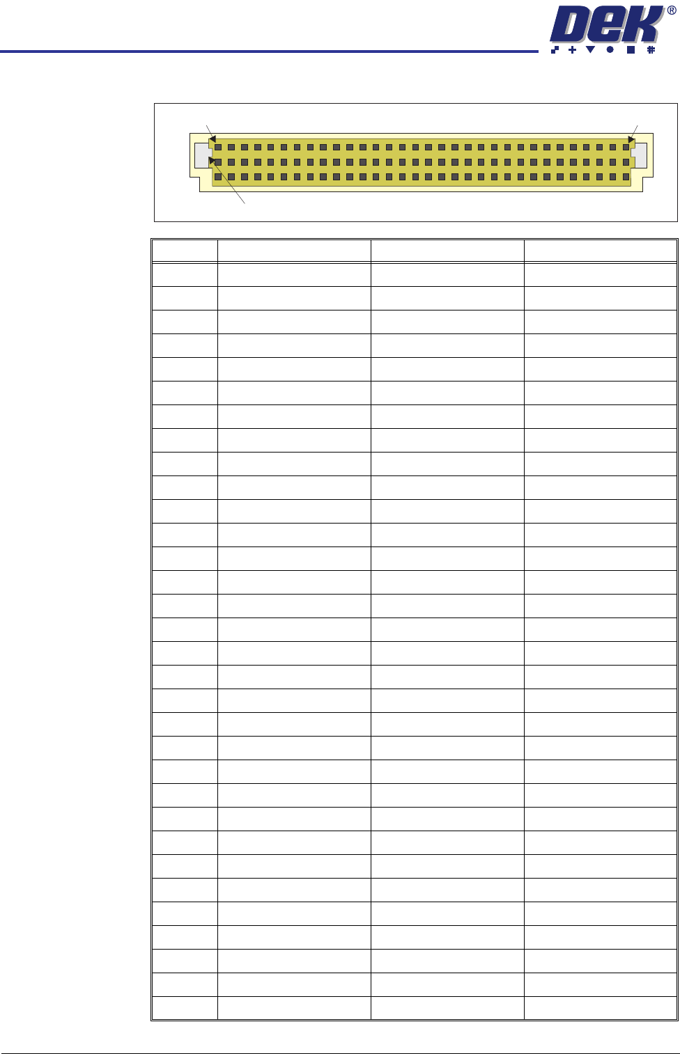
The edge connector connects the card to the backplane of the enclosure.
Pin No. Row a Row b Row c
1 24V US 24V US N/C
2 24V SW 24V SW N/C
3 N/C N/C Error Out (NextMove)
4 DIN0 (NextMove) DIN0 (Machine) DOUT1 (NextMove)
5 DIN1 (NextMove) DIN1 (Machine) DOUT2 (NextMove)
6 DIN2 (NextMove) DIN2 (Machine) DOUT3 (NextMove)
7 DIN3 (NextMove) DIN3 (Machine) DOUT4 (NextMove)
8 DIN4 (NextMove) DIN4 (Machine) DOUT5 (NextMove)
9 DIN5 (NextMove) DIN5 (Machine) DOUT6 (NextMove)
10 DIN6 (NextMove) DIN6 (Machine) DOUT7 (NextMove)
11 DIN7 (NextMove) DIN7 (Machine) N/C
12 DIN8 (NextMove) DIN8 (Machine) +12V
13 DIN9 (NextMove) DIN9 (Machine) N/C
14 DIN10 (NextMove) DIN10 (Machine) -12V
15 DIN11 (NextMove) DIN11 (Machine) N/C
16 DIN12 (NextMove) DIN12 (Machine) +5.5V
17 DIN13 (NextMove) DIN13 (Machine) N/C
18 DIN14 (NextMove) DIN14 (Machine) DGND
19 DIN15 (NextMove) DIN15 (Machine) N/C
20 DIN16 (NextMove) DIN16 (Machine) N/C
21 DIN17 (NextMove) DIN17 (Machine) N/C
22 DIN18 (NextMove) DIN18 (Machine) N/C
23 DIN19 (NextMove) DIN19 (Machine) N/C
24 N/C N/C N/C
25 0V (24V US Return) 0V (24V US Return) N/C
26 0V (24V SW Return) 0V (24V SW Return) N/C
27 N/C E Stop Supply DOUT4 (Machine)
28 N/C DOUT1 (Machine) DOUT5 (Machine)
29 N/C DOUT2 (Machine) DOUT6 (Machine)
30 !DOUT3 (Machine) DOUT3 (Machine) DOUT7 (Machine)
31 N/C N/C N/C
32 N/C N/C N/C
a
b
c
1 32
Keyway
MACHINE CONTROL
M36 MACHINE CONTROL ENCLOSURE
Chapter Issue 8 Oct 06 Technical Reference Manual 7.13
Dual Stepper Drive
Card
CAUTION
ANTI-STATIC HANDLING.
Standard precautions must be adhered to when
handling electronic cards and configuring and inserting into the enclo-
sures.
The dual stepper drive card consists of two identical stepper motor drive circuits
used to drive two stepper motors, in half-step mode.
Each of the twin channels of this card consists of an IC (A3977SED) which
combines the conversion of the Step and Direction inputs into control signals for
the output to the stepper motor. These control signals sequence the current in
each of a pair of DMOS (Diffused Metal Oxide Semiconductor) H-bridge motor
drivers.
The card is connected to both the +24V SW and +24V US supplies. The
switched (SW) supply is protected by a diode-fuse transient suppressor circuit.
The diode operates over an extremely short time period, enabling the circuit to
absorb voltage spikes without rupturing the fuse (F1 - 4Amp). If a sustained
voltage is experienced above its rating, the fuse ruptures. The +24V US is used
to produce an internally regulated +5.5V (VCC and VDD).
Whilst the stepper motor is stationary, the card switches to half power to
minimize power consumption.
The card utilizes the mixed decay feature of the IC to achieve the best sinusoidal
motor current waveform for stepper motors. This decreases current ripple and
hence decreases motor heating.
Each channel has a separate dipswitch which enables various circuit functions
and are shown in the table below:
Dipswitch Function
1 Enables Full/Half/Quarter/Eighth Step Operation
2 Enables Full/Half/Quarter/Eighth Step Operation
3 Half Power Timer Enable
4INV_STEP
5INV_DIR
6 Sets Motor Current Output
7 Sets Motor Current Output
8 Sets Motor Current Output
9 Percent Fast Decay_0
10 Percent Fast Decay_1