Printer 710_810 v8 Machine Control.pdf - 第15页
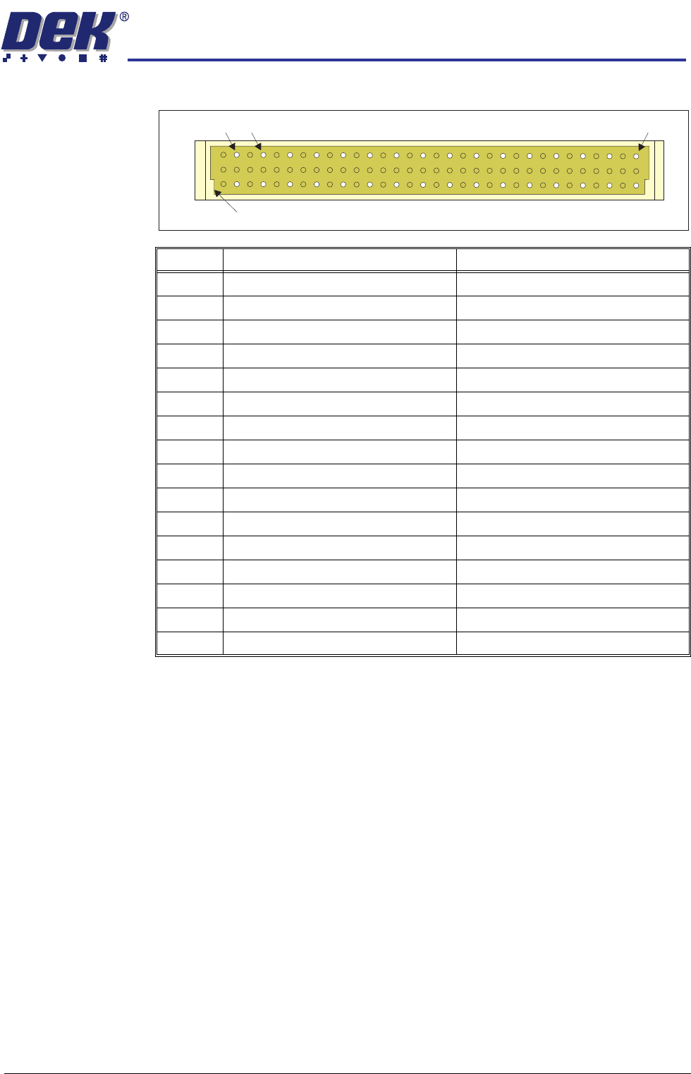
MACHI NE CONT ROL M36 MA CHINE CONTR OL EN CLOSUR E Chapter Issue 8 Oct 06 Technical Reference Manual 7.15 S tepper Drive Card Edge Connector The edge connector connect s the card to the backplane of the enclosur e. Pin …
MACHINE CONTROL
M36 MACHINE CONTROL ENCLOSURE
7.14 Technical Reference Manual Chapter Issue 8 Oct 06
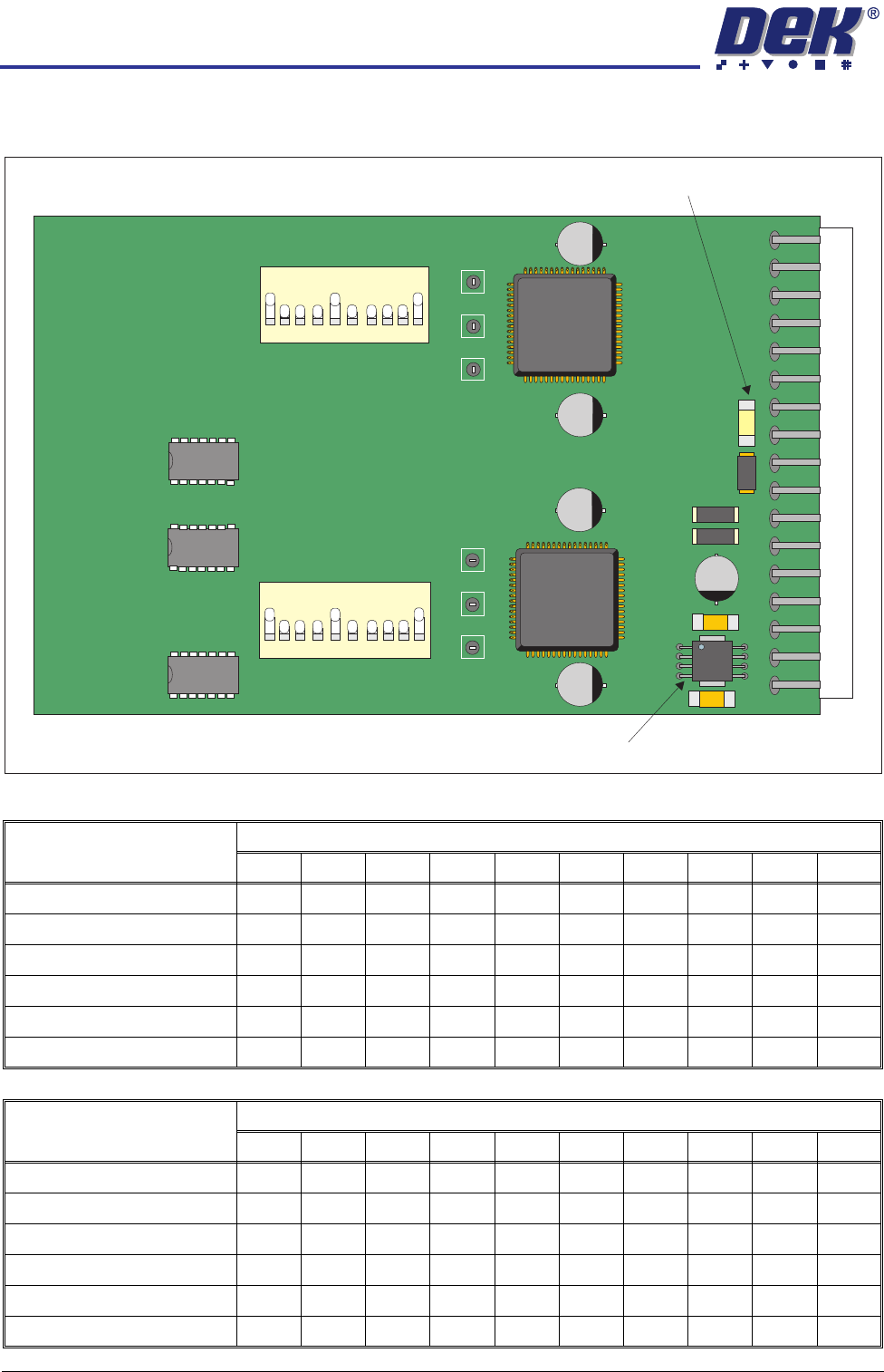
Dipswitch Settings Use the following graphic and tables to determine the correct dipswitch settings:
Figure 7-7 Dual Stepper Drive Card
Card Position and Dipswitch
Switch Positions (Standard Machine)
12345678910
Slot X1 - SW 1 OFF ON ON ON ON OFF ON ON ON OFF
Slot X1 - SW 2 OFF ON ON ON ON OFF ON ON ON OFF
Slot X2 - SW 1 OFF ON ON ON ON OFF ON ON ON OFF
Slot X2 - SW 2 OFF ON ON ON ON OFF ON ON ON OFF
Slot X3 - SW 1 OFF ON ON ON ON OFF ON ON ON OFF
Slot X3 - SW 2 OFF ON ON ON ON OFF ON ON ON OFF
Card Position and Dipswitch
Switch Positions (RTC Machine)
12345678910
Slot X1 - SW 1 OFF ON ON ON ON OFF ON ON ON OFF
Slot X1 - SW 2 OFF ON ON ON ON OFF ON ON ON OFF
Slot X2 - SW 1 OFF ON ON ON ON OFF ON ON ON OFF
Slot X2 - SW 2 OFF ON ON ON ON OFF ON ON ON OFF
Slot X3 - SW 1 OFF ON ON ON ON OFF ON ON ON OFF
Slot X3 - SW 2 OFF ON ON ON ON ON OFF OFF ON OFF
12
3
4
56
7
8
9
10
SW1
12
3
4
56
7
8
9
10
ON
ON
SW2
5V Regulator
Fuse F1
MACHINE CONTROL
M36 MACHINE CONTROL ENCLOSURE
Chapter Issue 8 Oct 06 Technical Reference Manual 7.15
Stepper Drive Card
Edge Connector
The edge connector connects the card to the backplane of the enclosure.
Pin No. Row a Row c
2 CH1 B- CH2 B-
4 CH1 B+ CH2 B+
6 CH1 A- CH2 A-
8 CH1 A+ CH2 A+
10 24V SW 24V SW
12 24V US 24V SW
14 24V US 24V SW
16 GND GND
18 GND GND
20 N/C N/C
22 N/C N/C
24 IDAT ICLK
26 IVPP DIR1
28 VCC OUT STEP1
30 DIR2 STEP2
32 N/C N/C
a
c
2 32
Keyway
4
MACHINE CONTROL
M36 MACHINE CONTROL ENCLOSURE
7.16 Technical Reference Manual Chapter Issue 8 Oct 06
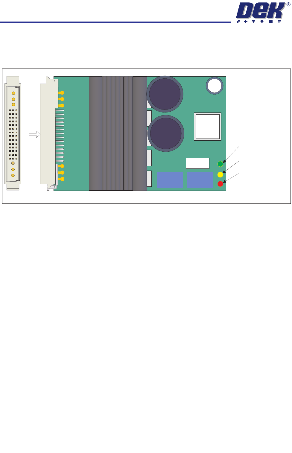
Servo Drive Card On linear drive machines only, two servo drive cards are used by the machine
controller to drive the camera X and Y axis motors. The axes for these motors
are designated Axis 0 and 1.
Figure 7-8 Servo Drive Card Layout (for linear motors)
A
View on A
C1 B1 A1
Card Error
(includes system
power off)
Card Disabled
(by software control)
Card Powered
(no errors)