Printer 710_810 v8 Machine Control.pdf - 第3页
MACHI NE CONT ROL ELECTRIC AL SCHEMA TIC Chapter Issue 8 Oct 06 Technical Reference Manual 7.3 ELECTRICAL SCHEMATIC Figure 7-1 St andard Machine NextMove Interface 20 Digital Input s 8 Digital Outputs I/O Node 4 Board (S…

MACHINE CONTROL
OVERVIEW
7.2 Technical Reference Manual Chapter Issue 8 Oct 06
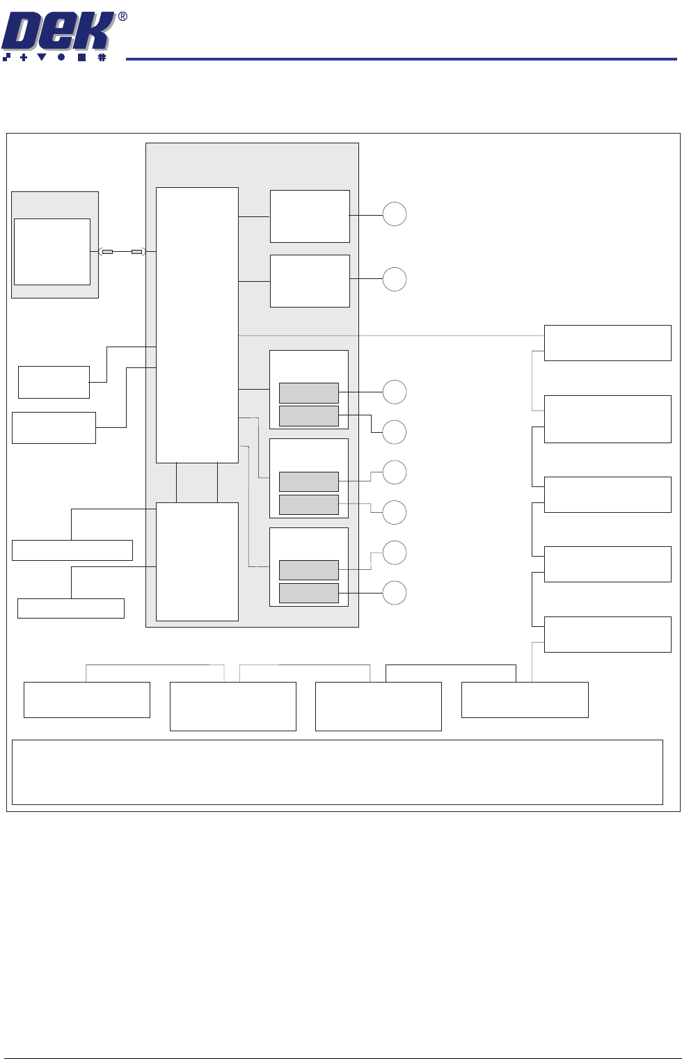
All machine functions are initiated by the DEK software installed on the PC. The
PC transmits and receives information to the NextMove ES card in the M36
Machine Control Enclosure using a single USB lead. The NextMove ES card
incorporates its own processor which handles machine motions and switch/
sensor feedback, this frees up the PC processor to run the MMI and other
peripherals.
The NextMove ES card incorporates a USB encoder/decoder and a CAN
encoder/decoder interfacing between the PC and the following:
• NextMove Interface Card
• Stepper Drive Cards
• EF Servo Drive Cards
• I/O Node Boards (via CAN Bus)
• Servo/Stepper Nodes (via CAN Bus)
MACHINE CONTROL
ELECTRICAL SCHEMATIC
Chapter Issue 8 Oct 06 Technical Reference Manual 7.3
ELECTRICAL SCHEMATIC
Figure 7-1 Standard Machine
NextMove
Interface
20 Digital Inputs
8 Digital Outputs
I/O Node 4 Board
(Screen Cleaner)
Servo Node 8
(Camera X Motor)
(Rotary Motors Only)
CAN Terminator
Servo Node 9
(Camera Y Motor)
(Rotary Motors Only)
I/O Node 2 Board
(Main Machine)
Stepper Node 10
(Paste Dispense
Stepper Motor)
Servo Node 6
(Rising Table Motor)
Servo Node 7
(Print Carriage Motor)
I/O Node 3 Board
(Print Carriage)
PC
USB
Motherboard
NextMove ES
(I/O Node 1)
4 Analogue
Outputs
2 Analogue
Inputs
Dual Stepper
Card X3
Step 2
Step 5
Dual Stepper
Card X2
Step 3
Step 4
Dual Stepper
Card X1
Step 0
Step 1
M
X Forward Actuator
M
Front Squeegee
M
Y Actuator
M
X Rear Actuator
M
Rear Squeegee
M
Moving Rail
I/Ps O/Ps
M36 Machine Control Enclosure
CAN Bus
EuroFlex
Card X6
Axis 0
M
Camera X Motor (Linear Motors Only)
M
Camera Y Motor (Linear Motors Only)
EuroFlex
Card X7
Axis 1
NOTE
Dependant upon configuration the servo drive consists of either servo nodes 8 and 9 (rotary motor systems) or
two EuroFlex cards for the Camera X and Camera Y axes (linear motor systems). The linear motor system uses 2
analogue ouputs from the NextMove ES card and 2 digital inputs from the NextMove Interface card.
MACHINE CONTROL
ELECTRICAL SCHEMATIC
7.4 Technical Reference Manual Chapter Issue 8 Oct 06
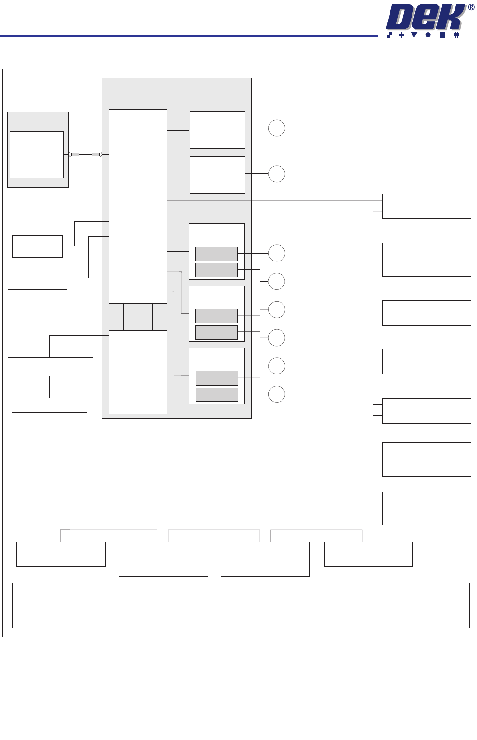
Figure 7-2 Rapid Transit Conveyor (RTC) Machine
NextMove
Interface
20 Digital Inputs
8 Digital Outputs
I/O Node 4 Board
(Screen Cleaner)
Servo Node 8
(Camera X Motor)
(Rotary Motors Only)
CAN Terminator
Servo Node 9
(Camera Y Motor)
(Rotary Motors Only)
I/O Node 2 Board
(Main Machine)
Servo Node 11
(Transport Mechanism
Servo Motor)
Stepper Node 12
(Moving Rail
Stepper Motor)
Stepper Node 10
(Paste Dispense
Stepper Motor)
Servo Node 6
(Rising Table Motor)
Servo Node 7
(Print Carriage Motor)
I/O Node 3 Board
(Print Carriage)
PC
USB
Motherboard
NextMove ES
(I/O Node 1)
4 Analogue
Outputs
2 Analogue
Inputs
Dual Stepper
Card X3
Step 2
Step 5
Dual Stepper
Card X2
Step 3
Step 4
Dual Stepper
Card X1
Step 0
Step 1
M
X Forward Actuator
M
Front Squeegee
M
Y Actuator
M
X Rear Actuator
M
Rear Squeegee
M
Vane Stepper Motor
I/Ps O/Ps
M36 Machine Control Enclosure
CAN Bus
EuroFlex
Card X6
Axis 0
M
Camera X Motor (Linear Motors Only)
M
Camera Y Motor (Linear Motors Only)
EuroFlex
Card X7
Axis 1
NOTE
Dependant upon configuration the servo drive consists of either servo nodes 8 and 9 (rotary motor systems) or
two EuroFlex cards for the Camera X and Camera Y axes (linear motor systems). The linear motor system uses 2
analogue ouputs from the NextMove ES card and 2 digital inputs from the NextMove Interface card.