Printer 710_810 v8 Machine Control.pdf - 第4页
MACHI NE CONT ROL ELECTRICA L SCHEMATIC 7.4 Technical Reference Manual Chapter Issue 8 Oct 06 Figure 7-2 Rapid T ransit Conveyor (RTC) Machine NextMove Interface 20 Digital Input s 8 Digital Outputs I/O Node 4 Board (Scr…
MACHINE CONTROL
ELECTRICAL SCHEMATIC
Chapter Issue 8 Oct 06 Technical Reference Manual 7.3
ELECTRICAL SCHEMATIC
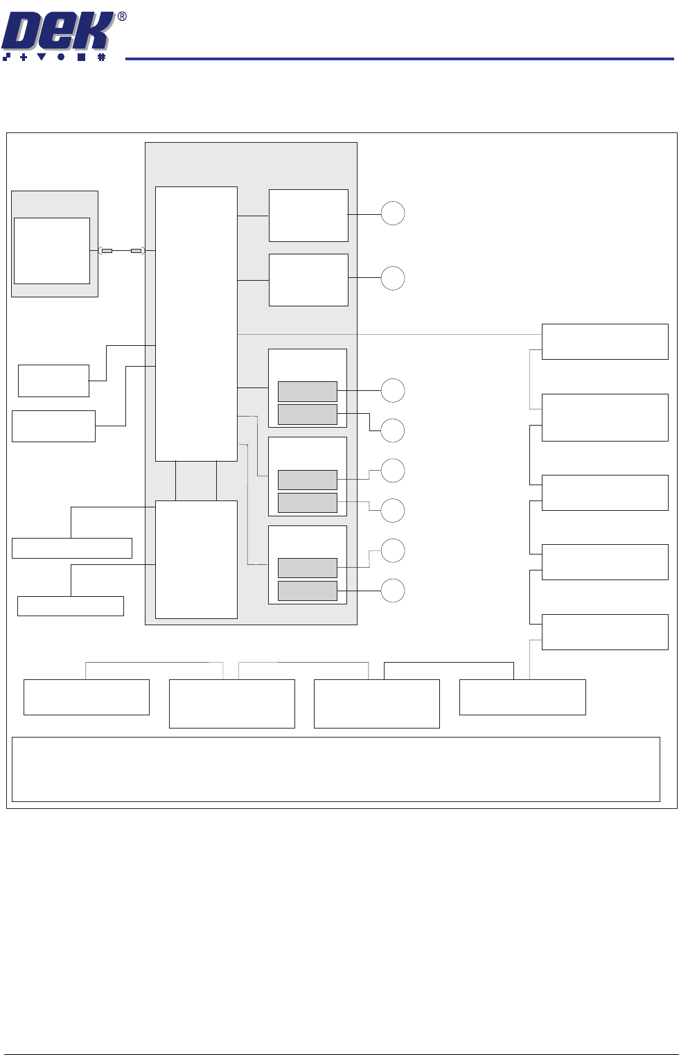
Figure 7-1 Standard Machine
NextMove
Interface
20 Digital Inputs
8 Digital Outputs
I/O Node 4 Board
(Screen Cleaner)
Servo Node 8
(Camera X Motor)
(Rotary Motors Only)
CAN Terminator
Servo Node 9
(Camera Y Motor)
(Rotary Motors Only)
I/O Node 2 Board
(Main Machine)
Stepper Node 10
(Paste Dispense
Stepper Motor)
Servo Node 6
(Rising Table Motor)
Servo Node 7
(Print Carriage Motor)
I/O Node 3 Board
(Print Carriage)
PC
USB
Motherboard
NextMove ES
(I/O Node 1)
4 Analogue
Outputs
2 Analogue
Inputs
Dual Stepper
Card X3
Step 2
Step 5
Dual Stepper
Card X2
Step 3
Step 4
Dual Stepper
Card X1
Step 0
Step 1
M
X Forward Actuator
M
Front Squeegee
M
Y Actuator
M
X Rear Actuator
M
Rear Squeegee
M
Moving Rail
I/Ps O/Ps
M36 Machine Control Enclosure
CAN Bus
EuroFlex
Card X6
Axis 0
M
Camera X Motor (Linear Motors Only)
M
Camera Y Motor (Linear Motors Only)
EuroFlex
Card X7
Axis 1
NOTE
Dependant upon configuration the servo drive consists of either servo nodes 8 and 9 (rotary motor systems) or
two EuroFlex cards for the Camera X and Camera Y axes (linear motor systems). The linear motor system uses 2
analogue ouputs from the NextMove ES card and 2 digital inputs from the NextMove Interface card.
MACHINE CONTROL
ELECTRICAL SCHEMATIC
7.4 Technical Reference Manual Chapter Issue 8 Oct 06
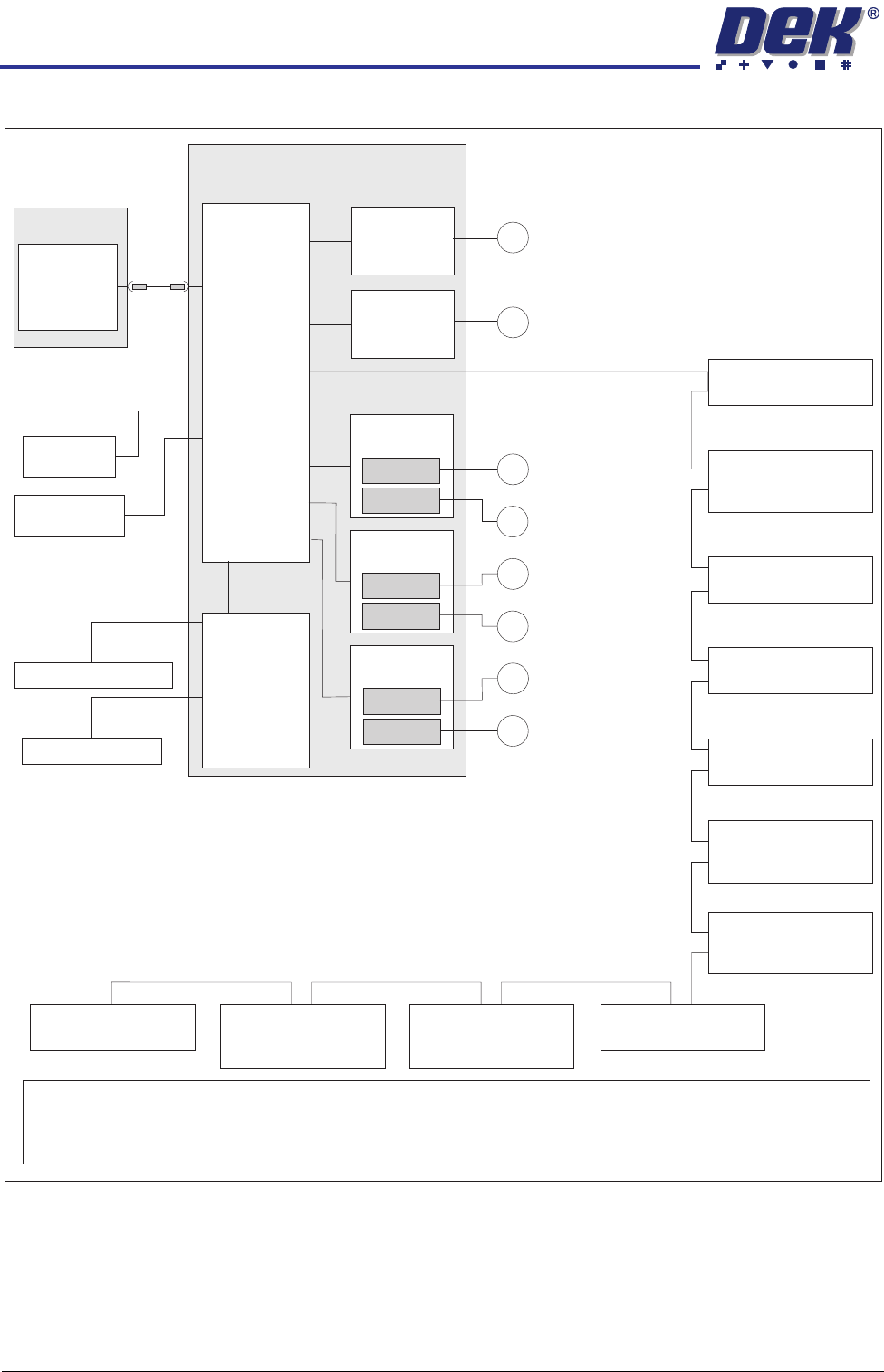
Figure 7-2 Rapid Transit Conveyor (RTC) Machine
NextMove
Interface
20 Digital Inputs
8 Digital Outputs
I/O Node 4 Board
(Screen Cleaner)
Servo Node 8
(Camera X Motor)
(Rotary Motors Only)
CAN Terminator
Servo Node 9
(Camera Y Motor)
(Rotary Motors Only)
I/O Node 2 Board
(Main Machine)
Servo Node 11
(Transport Mechanism
Servo Motor)
Stepper Node 12
(Moving Rail
Stepper Motor)
Stepper Node 10
(Paste Dispense
Stepper Motor)
Servo Node 6
(Rising Table Motor)
Servo Node 7
(Print Carriage Motor)
I/O Node 3 Board
(Print Carriage)
PC
USB
Motherboard
NextMove ES
(I/O Node 1)
4 Analogue
Outputs
2 Analogue
Inputs
Dual Stepper
Card X3
Step 2
Step 5
Dual Stepper
Card X2
Step 3
Step 4
Dual Stepper
Card X1
Step 0
Step 1
M
X Forward Actuator
M
Front Squeegee
M
Y Actuator
M
X Rear Actuator
M
Rear Squeegee
M
Vane Stepper Motor
I/Ps O/Ps
M36 Machine Control Enclosure
CAN Bus
EuroFlex
Card X6
Axis 0
M
Camera X Motor (Linear Motors Only)
M
Camera Y Motor (Linear Motors Only)
EuroFlex
Card X7
Axis 1
NOTE
Dependant upon configuration the servo drive consists of either servo nodes 8 and 9 (rotary motor systems) or
two EuroFlex cards for the Camera X and Camera Y axes (linear motor systems). The linear motor system uses 2
analogue ouputs from the NextMove ES card and 2 digital inputs from the NextMove Interface card.
MACHINE CONTROL
M36 MACHINE CONTROL ENCLOSURE
Chapter Issue 8 Oct 06 Technical Reference Manual 7.5
M36 MACHINE CONTROL ENCLOSURE
The M36 Machine Control Enclosure is located at the rear of the machine and
interfaces between the PC and machine motors, sensors and switches. The
PC connects to the M36 with a USB cable allowing two-way communications
between the two enclosures.
The M36 enclosure has a single backplane PCB with edge connectors mounted
on one side for plug-in cards (Slot X1 - X7) and plugs and sockets on the other
side, protruding through the rear panel, for connection to the machine looms.
The front panel has a cut-out slot to allow connection of the USB and CAN Bus
cables to the NextMove ES card in Slot X5.
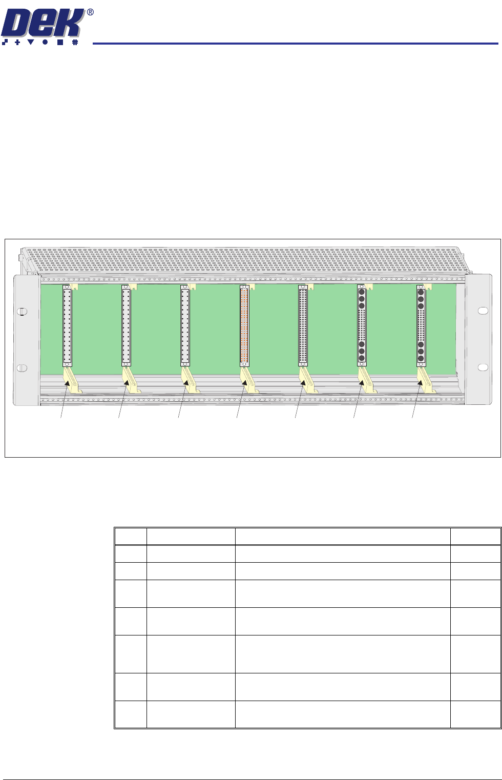
M36 Card Locations
Card Placement
CAUTION
ANTI-STATIC HANDLING.
Standard precautions must be adhered to when
handling electronic cards and configuring and inserting into the enclo-
sures.
Slot X1 Slot X2 Slot X3 Slot X4 Slot X5 Slot X6 Slot X7
View on Front (front panel removed)
Slot Card Function Step/Axis
X1 Dual Stepper X Forward and X Rear Actuators Step 0,1
X2 Dual Stepper Front and Rear Squeegees Step 3,4
X3 Dual Stepper Y Actuator and Moving Rail/Vane Stepper Motor
(RTC machine)
Step 2,5
X4 NextMove Interface Opto-isolates 20 inputs and 8 outputs from the
NextMove ES card
X5 NextMove ES
(I/O Node1)
Motion control card providing 6 stepper and 2 servo
axes with real time I/O. Also acts as a CAN master
interfacing between the USB and CAN buses
X6 EF Servo Drive Camera X Linear Servo Motor
(linear drive machines only)
Axis 0
X7 EF Servo Drive Camera Y Linear Servo Motor
(linear drive machines only)
Axis 1