Printer 710_810 v8 Machine Control.pdf - 第42页
MACHI NE CONT ROL CAN BUS 7.42 Technical Reference Manual Chapter Issue 8 O ct 06 N3SK16 N3SK17 Pin No. Signal Pin No . Signal 10 V 6N / C 2N / C 7B r i d g e O / P + 3N / C 8B r i d g e O / P - 4N / C 9N / C 5+ 4 . 1 V …
MACHINE CONTROL
CAN BUS
Chapter Issue 8 Oct 06 Technical Reference Manual 7.41
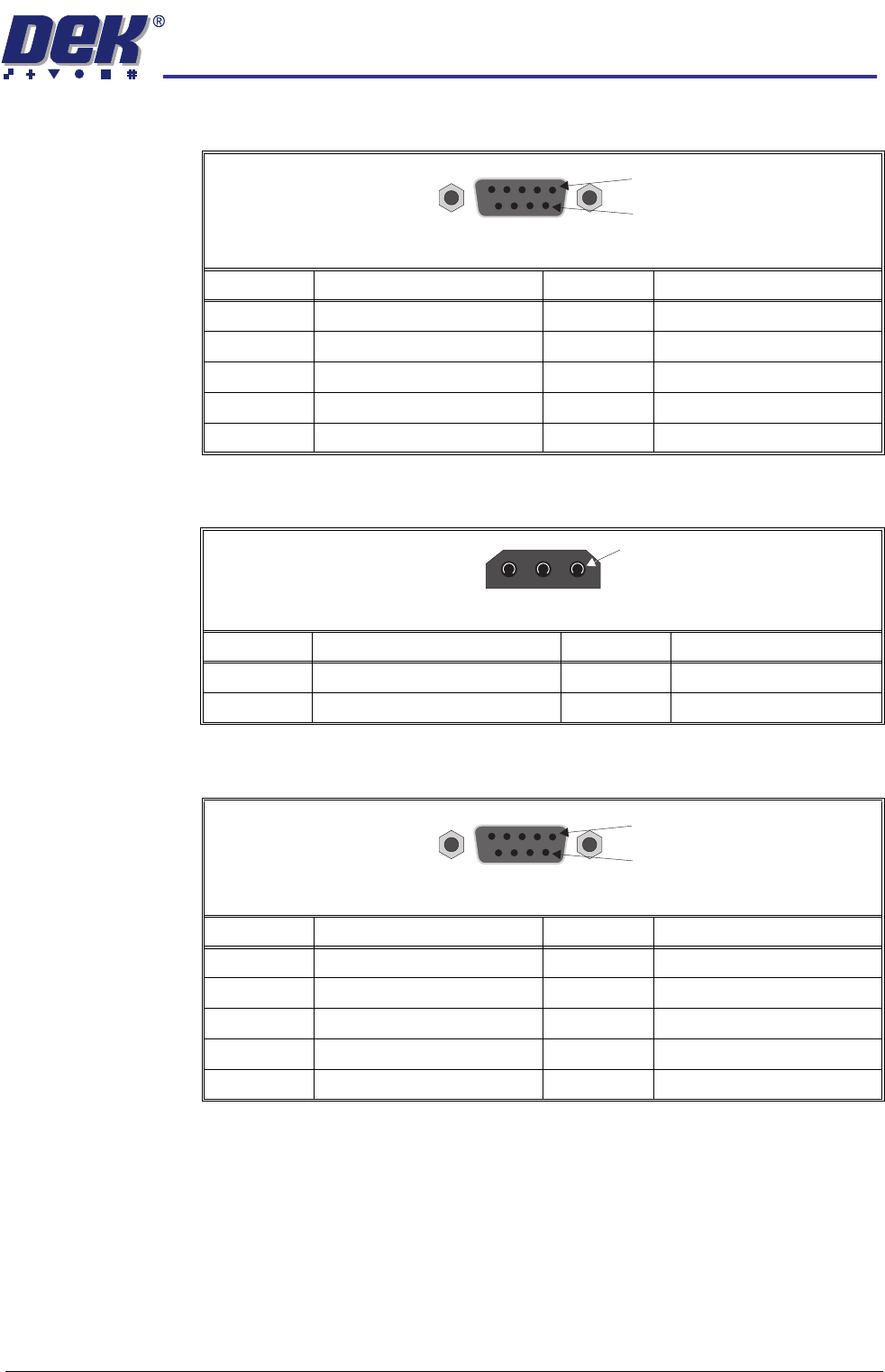
N3SK13
N3SK14
N3SK15
Pin No. Signal Pin No. Signal
1 24V US 6 ProFlow Pressure Demand
20V 724V US
3 Spare Output 8 0V
4 12V 9 ProFlow Pressure Monitor
50V
9Way DType Socket
1
6
Pin No. Signal Pin No. Signal
1+12V 30V
2 Ball Escape (Ball Bumping only)
1
3Way Trident Connector
Pin No. Signal Pin No. Signal
1I DAT 65.5V
20V 7I CLOCK
3DAT_INT 8IO_B
4 VPP 9 0V
5IO_C
9Way DType Socket
1
6
MACHINE CONTROL
CAN BUS
7.42 Technical Reference Manual Chapter Issue 8 Oct 06
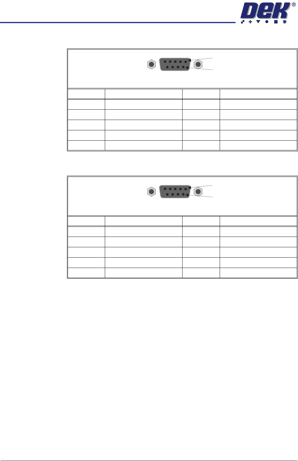
N3SK16
N3SK17
Pin No. Signal Pin No. Signal
10V 6N/C
2N/C 7Bridge O/P +
3N/C 8Bridge O/P -
4N/C 9N/C
5+4.1V
9Way DType Socket
1
6
Pin No. Signal Pin No. Signal
1 +12V 6 0V
2 0V 7 ProFlow Cassette Low
3 Paste Level 8 0V
4+12V 9+12V
5 ProFlow Fitted
9Way DType Socket
1
6
MACHINE CONTROL
CAN BUS
Chapter Issue 8 Oct 06 Technical Reference Manual 7.43
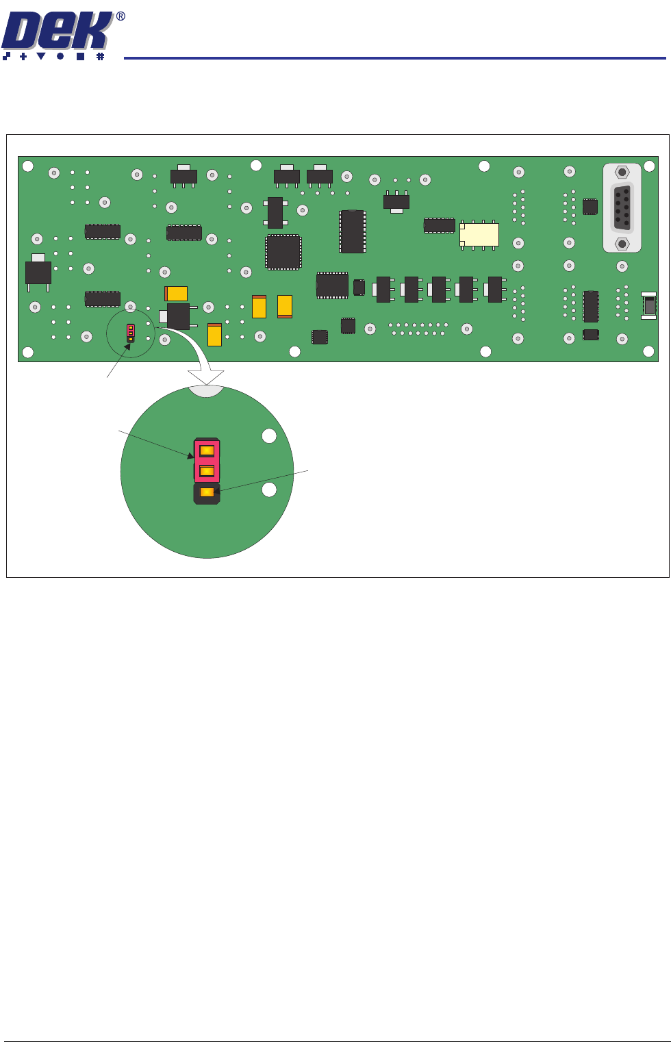
Link (LK1) The link LK1 on the component side of I/O node board 3 must be set so that the
jumper is shorting out Pins 1 & 2.
3
View on Component Side of Board
N3SK16
Link (LK1)
3
Jumper
Pin 3