00195089-0102_AI_Vakuumpumpe_X-Serie_60X_DE+EN.pdf - 第106页
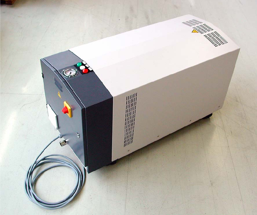
Assembly Instructions SIPLACE Vacuum Pump Ausgabe 07/2006 102 Fig. 2.10.1 V acuum pump with pressure gauge, control lamp, main s witch, power cable and v acuum connectio n.

Assembly Instructions SIPLACE Vacuum Pump
Ausgabe 07/2006
101
2.10 Vacuum Pump
2
Please follow the safety instructions in Chapter 2.5.
2
The vacuum pump must be installed according to the pump manufacturer’s (Gardner Denver
Elmo Technology GmbH) instructions. Refer to the operating instructions for the vacuum pump
system series 2SH: Chapter 5.2. Connect Electric System. 2
2
2
The side channel vacuum pump is, depending on machine configuration, set up for a maximum
of 4 placement machines. If a X4 machine with 4 C&P20 heads is used, one vacuum pump can
supply a maximum of one placement machine. 2
2
2
The vacuum pump must run as long as one of the consumer loads is in operation. 2
2
2
The vacuum pump is started with the control cable. The placement machine only starts if enough
low pressure is created in that machine (ready at the earliest starting with SW version 603). 2
2
So that not all connected placement machines must be turned off to service a single placement
machine, it is useful to build shut-off valves into the vacuum hoses (between the Y connector and
the vacuum distributor one shut-off valve each, so that each vacuum hose can be shut off
separately). 2
Assembly Instructions SIPLACE Vacuum Pump
Ausgabe 07/2006
102
Fig. 2.10.1 Vacuum pump with pressure gauge, control lamp, main switch, power cable and vacuum connection.
Assembly Instructions SIPLACE Vacuum Pump
Ausgabe 07/2006
103
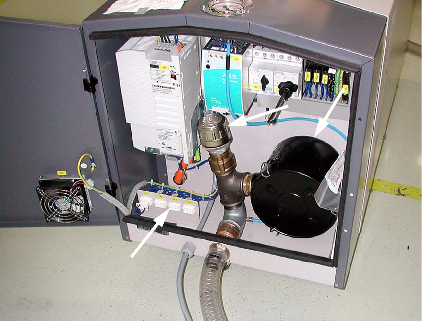
Fig. 2.10.2 Open vacuum pump
(1) Factory-adjusted pressure limit valve
(2) Air filter
(3) Control connectors for 4 placement machines
2
: Fasten the vacuum hose (siphon and pressure hose) with a hose clamp.
: Trim the vacuum pump with a knife or wire cutter, based on your set-up.
: Secure the Y connector on the other end.
: Run one vacuum hose each to the individual placement machines.