00195089-0102_AI_Vakuumpumpe_X-Serie_60X_DE+EN.pdf - 第113页
Assembly Instructions SIPLACE Vacuum Pump Ausgabe 07/2006 109 Fig. 2.11.2 C&P20 with porous muffler (for compressed air) 2 Please take care not to soil or damage the camera optics. : Loosen the muf fler ’s fastening …
Assembly Instructions SIPLACE Vacuum Pump
Ausgabe 07/2006
108
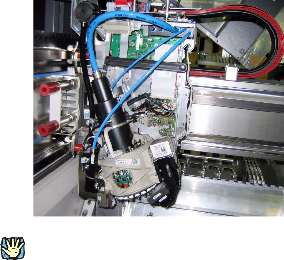
Fig. 2.11.1 C&P20, fitted with hoses for compressed air (starting position)
2
Before any work is performed the machine – after being properly shut down – must be turned off
at the main switch and separated from the power system. Thereafter the compressed air supply
must also be turned off at the compressed air unit’s main valve in the machine stand. The air
supply must then be ventilated by activating the needle valve on the compressed air unit.
.
Assembly Instructions SIPLACE Vacuum Pump
Ausgabe 07/2006
109
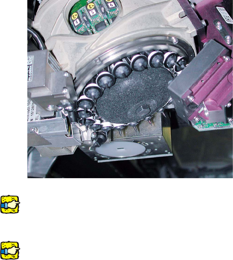
Fig. 2.11.2 C&P20 with porous muffler (for compressed air)
2
Please take care not to soil or damage the camera optics.
: Loosen the muffler’s fastening screw.
: Carefully li
ft the muffler from the machine.
2
Take care not to damage the DP drives. 2
2
2
2
2
Assembly Instructions SIPLACE Vacuum Pump
Ausgabe 07/2006
110
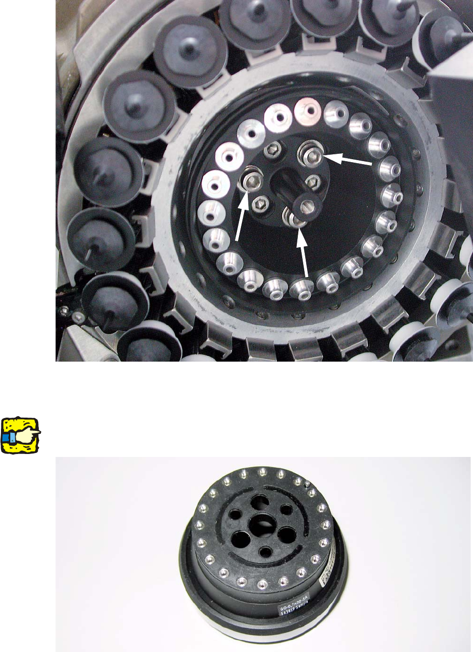
Fig. 2.11.3 C&P20 with holding circle vacuum unit (03005122-)
: Unscrew the three raised screws and remove the “vacuum unit holding circle C&P20”.
2
Before inserting the orifice ring, make sure that the seal washer (03046345-) is placed on the “ori-
fice ring C&P20” with the correct orientation. 2
Fig. 2.11.4 Orifice ring C&P20 with seal washer