00195089-0102_AI_Vakuumpumpe_X-Serie_60X_DE+EN.pdf - 第114页
Assembly Instructions SIPLACE Vacuum Pump Ausgabe 07/2006 110 Fig. 2.11.3 C&P20 with holding circle vacuum unit (03005122-) : Unscrew the three raised screws and remove the “vacuum unit holding circle C&P20”. 2 B…
Assembly Instructions SIPLACE Vacuum Pump
Ausgabe 07/2006
109
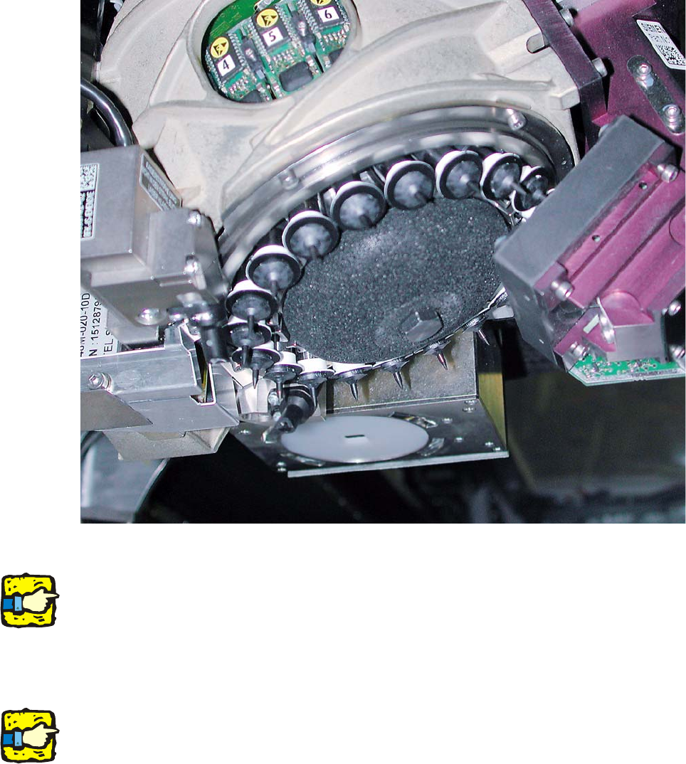
Fig. 2.11.2 C&P20 with porous muffler (for compressed air)
2
Please take care not to soil or damage the camera optics.
: Loosen the muffler’s fastening screw.
: Carefully li
ft the muffler from the machine.
2
Take care not to damage the DP drives. 2
2
2
2
2
Assembly Instructions SIPLACE Vacuum Pump
Ausgabe 07/2006
110
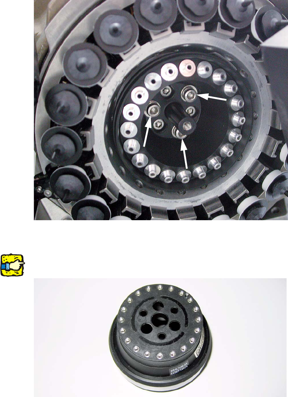
Fig. 2.11.3 C&P20 with holding circle vacuum unit (03005122-)
: Unscrew the three raised screws and remove the “vacuum unit holding circle C&P20”.
2
Before inserting the orifice ring, make sure that the seal washer (03046345-) is placed on the “ori-
fice ring C&P20” with the correct orientation. 2
Fig. 2.11.4 Orifice ring C&P20 with seal washer
Assembly Instructions SIPLACE Vacuum Pump
Ausgabe 07/2006
111
2
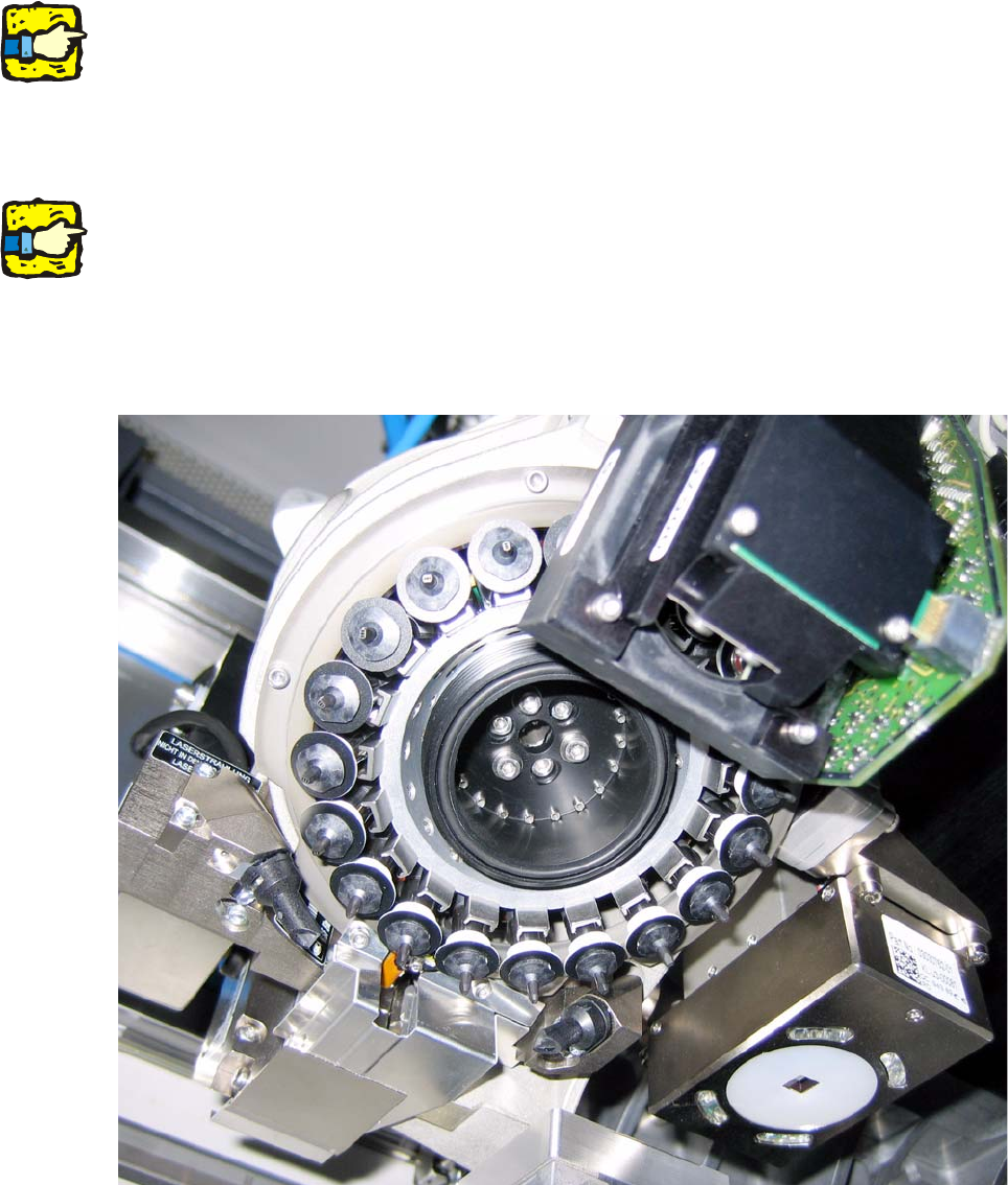
When inserting the new “orifice ring C&P20” ensure that the bolt is dipped into the appropriate
bore hole of the star bracket. The orifice ring should stick by itself. 2
2
: Carefully hold the star (when fastening the screws) at the star bracket in the area of the
segment guides.
2
Ensure that you don’t damage the faceplate switch and the pipettes. 2
2
: Now tighten the orifice ring all around using screws “DIN 912-M3 x10”. It should not tilt in the
process.
: Check whether the “O-Ring 42x2 NBR70” has been properly inserted into the orifice ring’s nut.
Fig. 2.11.5 C&P20 with orifice ring C&P20 (03046344-)