00195089-0102_AI_Vakuumpumpe_X-Serie_60X_DE+EN.pdf - 第116页
Assembly Instructions SIPLACE Vacuum Pump Ausgabe 07/2006 112 Fig. 2.11.6 C&P20 with cov er for the vacuum : Screw the cover (0 3046347-) hand-tightened onto the “orifice ring C&P20”. 2.1 1.1 Maintenance Every 4 …
Assembly Instructions SIPLACE Vacuum Pump
Ausgabe 07/2006
111
2
When inserting the new “orifice ring C&P20” ensure that the bolt is dipped into the appropriate
bore hole of the star bracket. The orifice ring should stick by itself. 2
2
: Carefully hold the star (when fastening the screws) at the star bracket in the area of the
segment guides.
2
Ensure that you don’t damage the faceplate switch and the pipettes. 2
2
: Now tighten the orifice ring all around using screws “DIN 912-M3 x10”. It should not tilt in the
process.
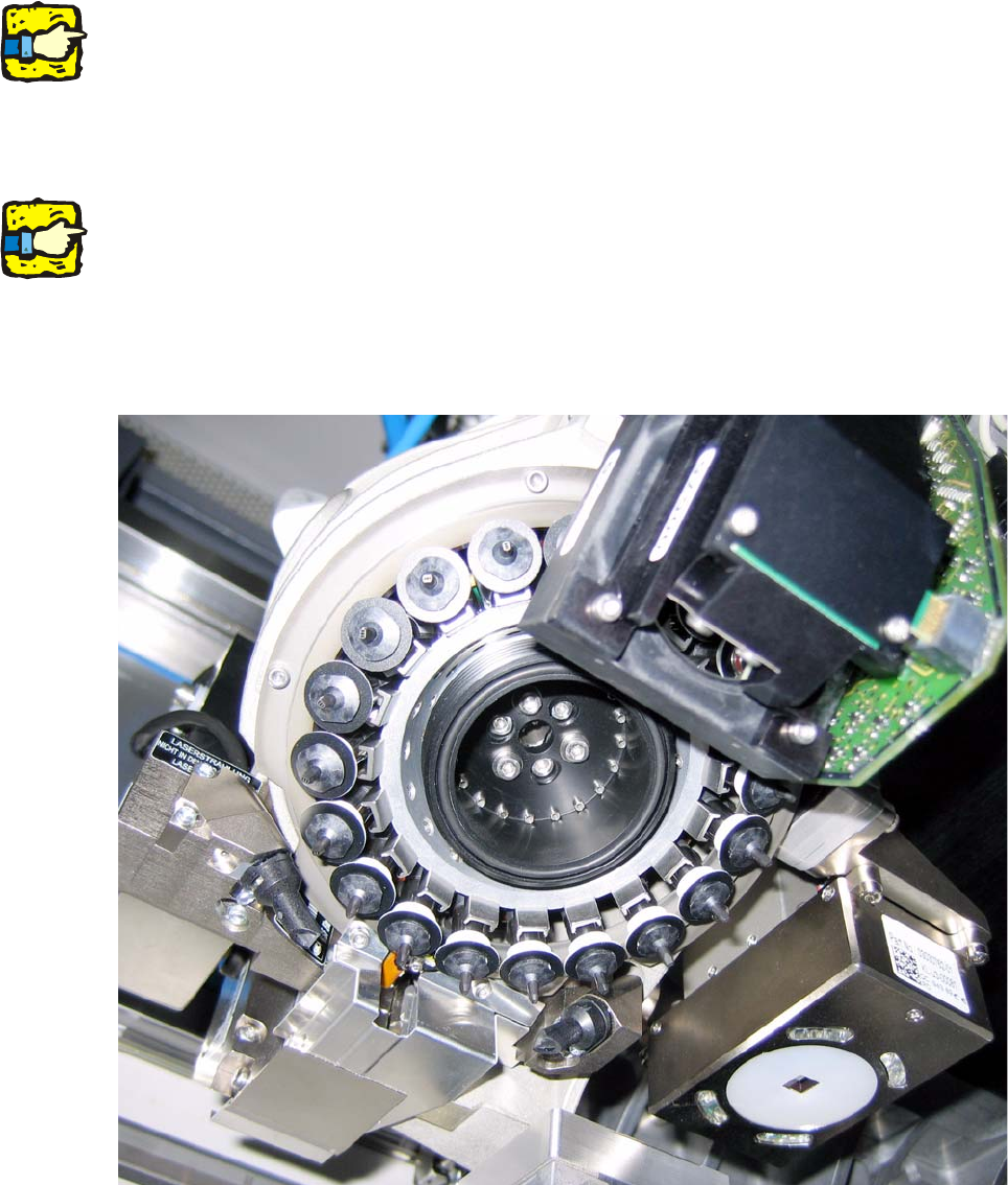
: Check whether the “O-Ring 42x2 NBR70” has been properly inserted into the orifice ring’s nut.
Fig. 2.11.5 C&P20 with orifice ring C&P20 (03046344-)
Assembly Instructions SIPLACE Vacuum Pump
Ausgabe 07/2006
112
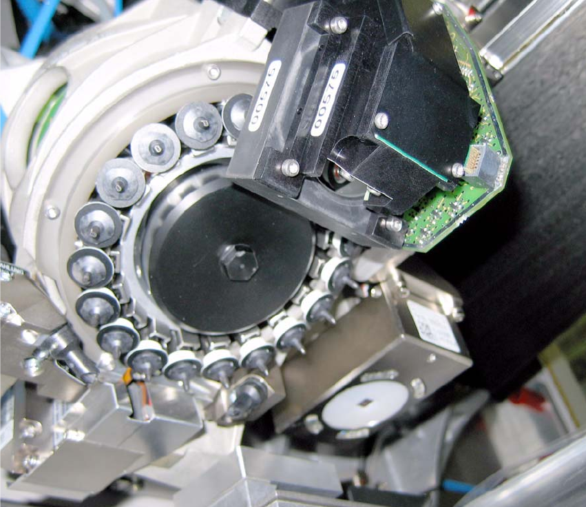
Fig. 2.11.6 C&P20 with cover for the vacuum
: Screw the cover (03046347-) hand-tightened onto the “orifice ring C&P20”.
2.11.1 Maintenance
Every 4 months: 2
: Check the “orifice ring complete C&P20” (03046348-) for soiling and replace it, if necessary.
2
Assembly Instructions SIPLACE Vacuum Pump
Ausgabe 07/2006
113
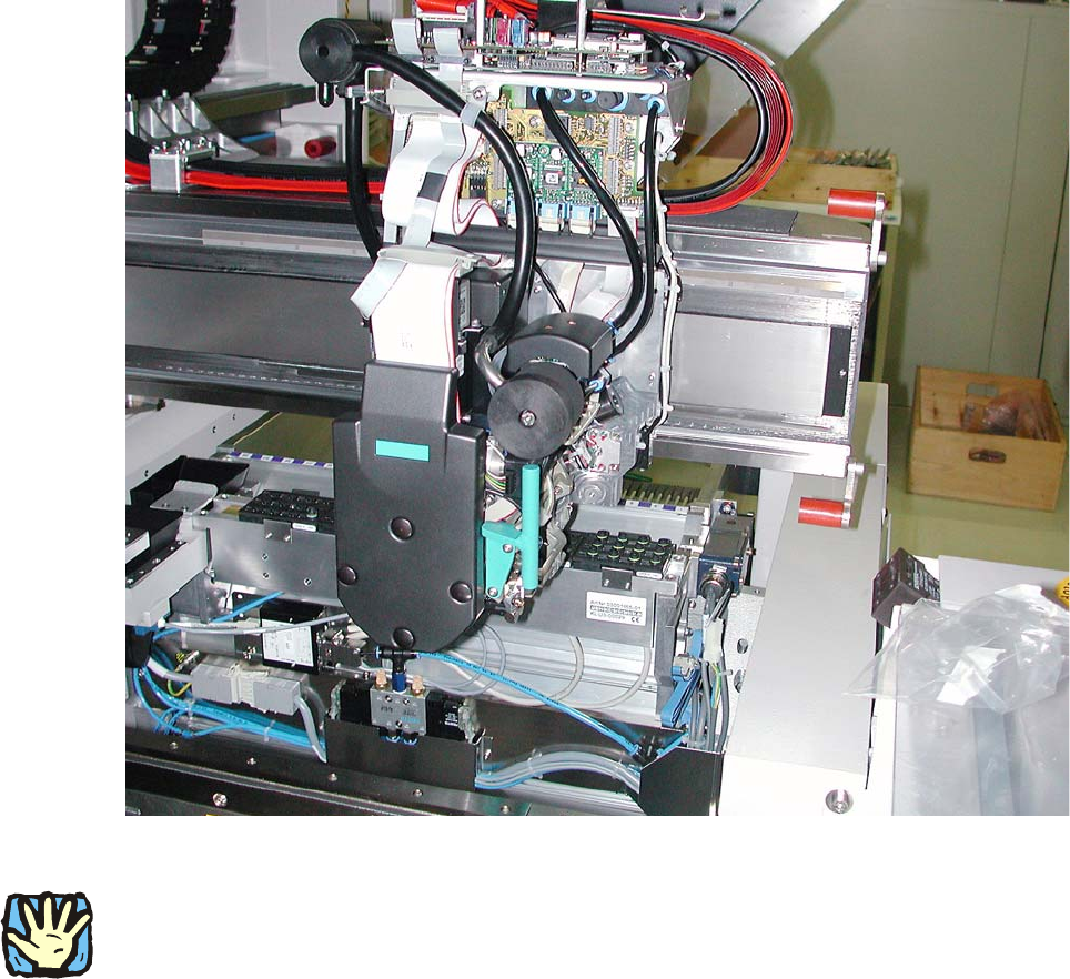
2.12 Retrofitting C&P12 and C&P6
Abb. 2.12.1 C&P12 with compressed air (starting position)
2
Before any work is performed the machine – after being properly shut down – must be turned off
at the main switch and separated from the power system. Thereafter the compressed air supply
must also be turned off at the compressed air unit’s main valve in the machine stand. The air
supply must then be ventilated by activating the needle valve on the compressed air unit.