00195089-0102_AI_Vakuumpumpe_X-Serie_60X_DE+EN.pdf - 第121页
Assembly Instructions SIPLACE Vacuum Pump Ausgabe 07/2006 117 2.14 Final W ork 2.14.1 Conditions for T urning the Machines on 2 Before turning the machines on, check the following to p revent injuries or ma jor property …
Assembly Instructions SIPLACE Vacuum Pump
Ausgabe 07/2006
116
2.13.3 Special Features of the C&P6/12 Placement Head
One vacuum pump can supply a maximum of 16 x C&P6/12 heads. 2
For the C&P6/12 a modified vacuum generator is inserted
at the C&P6/12 placement head. This
means the collection circuit is supplied by Venturi jets and the holding circle by the vacuum pump.2
If the placement head is in the waiting position, the star
is located between the two star positions
(half cycle). 2
In this intermediate position
the hold and collection circuits are connected via the grinder. If a
placement machine is turned off in this park position, the vacuum is lowered. This has
repercussions for the placement heads of all connected placement machines if no shut-off valves
have been inserted. 2
No interaction occurs among the placement machines conne
cted by the vacuum pump, even
without (closed) shut-off valves, only if the pipettes in the placement machine which is turned off
are in a vertical position. 2

Assembly Instructions SIPLACE Vacuum Pump
Ausgabe 07/2006
117
2.14 Final Work
2.14.1 Conditions for Turning the Machines on
2
Before turning the machines on, check the following to prevent injuries or major property damage:2
Before turning the compressed air back on, ensure that: 2
– all hose attachments and connectio
ns are co
rrectly allocated
(i.e. no compressed air flows into a vacuum hose)
–
all preconditions for turning on the vacuum pump and the placem
ent machines connected to it
have been followed as stated in the operating instructions.
– the vacuum pump is always turned on before the placement machine is turned on.
2
: Turn the vacuum pump on.
: If necessary, open the vacuum shut-off valves which have been inserted.
2
: Open the compressed air shut-off valve.
: Push the pneumatic unit into the placement machine.
: Close all doors.
: Turn on the main switch.
: Repeat above steps for all connected placement machines.
Assembly Instructions SIPLACE Vacuum Pump
Ausgabe 07/2006
118
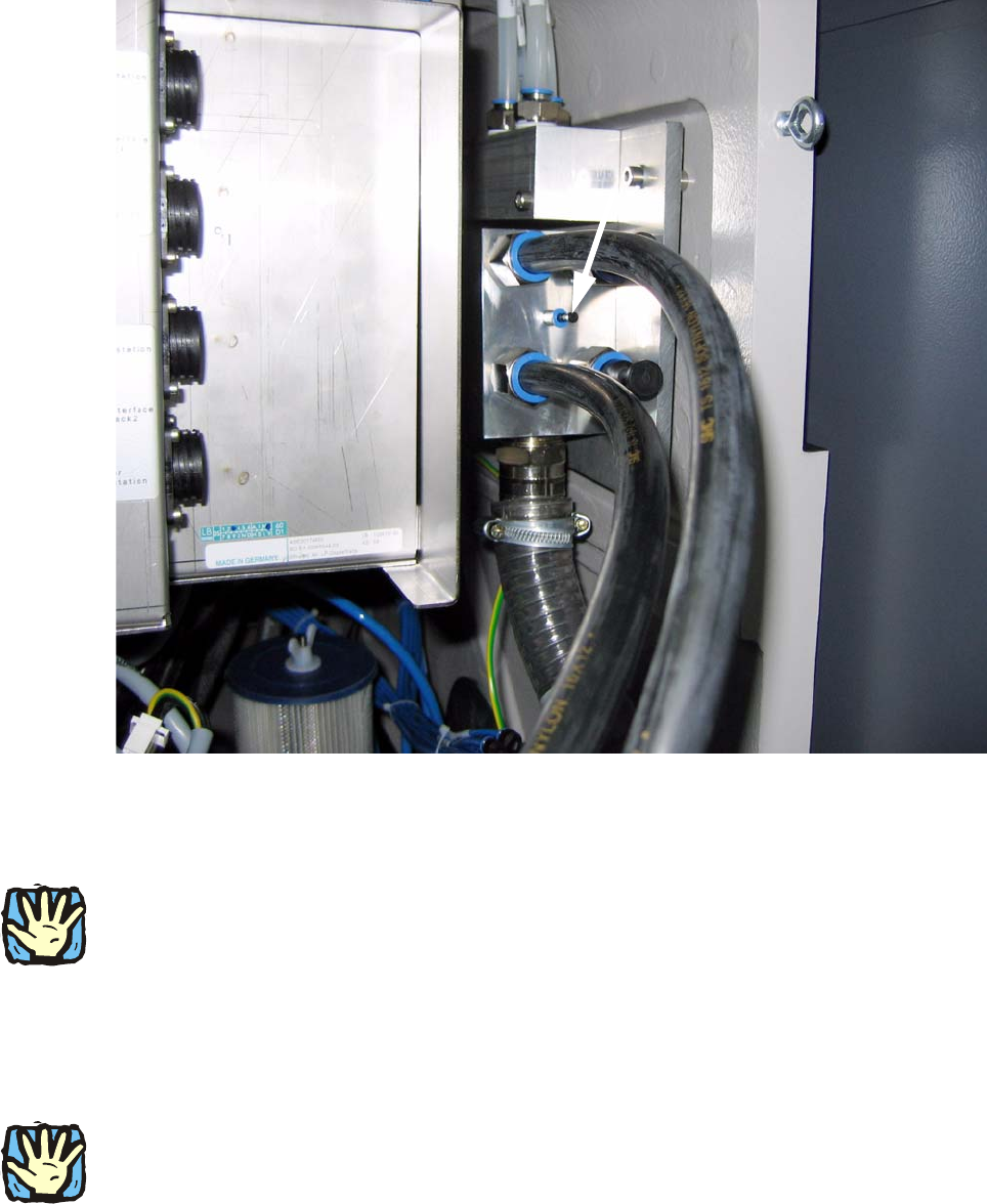
2.14.2 Inspection of Vacuum Circuit
Fig. 2.14.1 Measuring location at the vacuum distributor block (machine input)
2.14.2.1 Check Vacuum System of C&P20’s Holding Circle for Leak Tightness
2
2
Depending on the pipette configuration, at each placement machine/head a vacuum of at least
-500 mbar (for very large pipettes 1235) or -600 mbar (of very small pipettes 1006) should occur!2
Measuring occurs at a pipette with an external measurin
g device, which corresponds to a closed
pipette (with component). 2
2
Measuring location at the vacuum distributor block at machine input (see Fig. 2.14.1): 2
2
2
During operation the vacuum here should never fall below -400 mbar. If this occurs anyway,
please call the SIPLACE hotline. 2
2