00195089-0102_AI_Vakuumpumpe_X-Serie_60X_DE+EN.pdf - 第126页
Assembly Instructions SIPLACE Vacuum Pump Ausgabe 07/2006 122 Depending on pipette configura t ion, for mixed operation of C&P20 and C&P6/12 heads a vacuu m of at least -500 mbar ( very large pipettes 920) to - 6…
Assembly Instructions SIPLACE Vacuum Pump
Ausgabe 07/2006
121
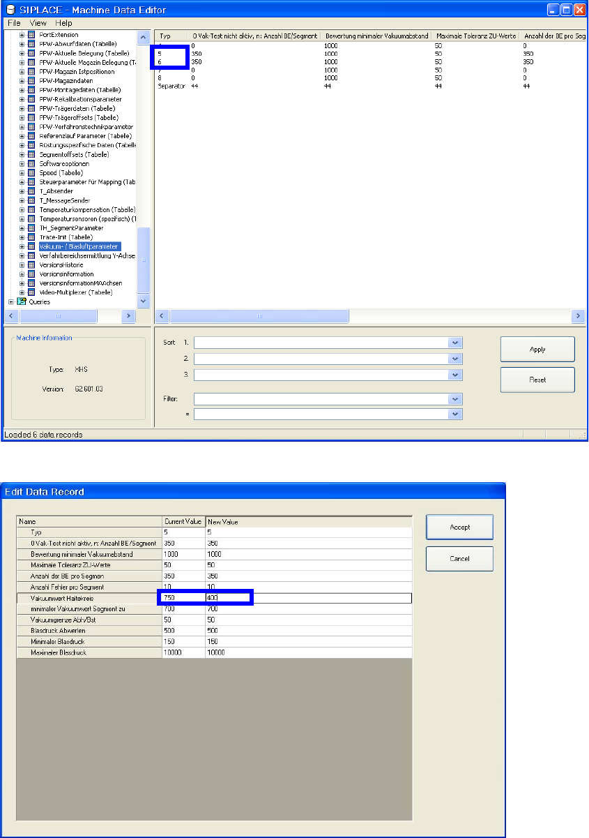
Fig. 2.14.2 Select table vacuum/bubble air parameters
Fig. 2.14.3 Correct vacuum values holding circle

Assembly Instructions SIPLACE Vacuum Pump
Ausgabe 07/2006
122
Depending on pipette configuration, for mixed operation of C&P20 and C&P6/12 heads a vacuum
of at least -500 mbar (very large pipettes 920) to -600 mbar (very small pipettes 906) should occur
at each placement machine/head! 2
If only C&P6/12 heads are used, the higher vacuum of
-600 mbar is generally reached since no
leakage air occurs because the jets are closed in this case (as opposed to the C&P20 head). 2
Procedure to Inspect the Leak Tightness of a C&P6/12 Head: 2
To prevent differences based on offset errors it makes sense to take both measurements with the
sa
me measur
ing device. 2
: Measure the vacuum with an external pressure measurement device:
– a
t the measurement location of the distributor
placement head at machine input (see Fig.
2.14.1)
and thereafter
– at an open pipette in the placement head’s holding circ
le. All other pipettes must be closed.
The pressure differential can be a max. of 20-30 mbar! Oth
erwise not everything is leak tight. 2
However, during the vacuum test of the holding circle with
closed pipettes a different value can be
shown if the vacuum plate has an offset. Measuring at the head and the vacuum distributor with
the same measurement device therefore makes sense. 2
2
The vacuum value for closed pipettes with attached vacuum pump in the holding circle is
generally approx. 200 to 300 mbar less than for the Venturi generator in the collect circuit (each
measured with an external measuring device at an (open) pipette in the collect circuit and an
(open) one in the holding circle). 2
If these values are not reached, the reason is usually a hose in the head
area which is not pulled
up all the way to the catch. Do the following: 2
: Re-squeeze all hoses with the tube gripper.
: Repeat the vacuum measurement.

Assembly Instructions SIPLACE Vacuum Pump
Ausgabe 07/2006
123
2.14.2.4 Inspect Entire Function of the C&P6/12’s Holding Circle Vacuum System
Throughput can be controlled correctly here based on the vacuum characteristic line, as opposed
to the C&P20 head. 2
Do the following: 2
: Remo
ve the pipettes from the placement head (to reach maximum throughput)
: Open in
SITEST the segments in collect position one after another and turn each in the star
rhythm into the holding circle.
The vacuum measurement in the holding circle shows a vacuum loss of approx. 10-30 mbar for
e
ach add
itionally opened pipette. 2
2
For six open pipettes the vacuum could e.g., fall from -580 mbar to -500 mbar. Because of the
discretionary combination of C&P20 and C&P6/12 heads on the same or different placement
machines (head modularity) it is not possible to state a fixed threshold for a minimally necessary
vacuum. For mixed operation with C&P20 heads the vacuum loss is generally significantly larger
than for operation with only C&P6/12 heads. 2