00195089-0102_AI_Vakuumpumpe_X-Serie_60X_DE+EN.pdf - 第82页
Assembly Instructions SIPLACE Vacuum Pump Ausgabe 07/2006 78 Fig. 2.7.8 Pneumatic unit with pressure connectors (connecto rs at star ting point). Mino r visual differences in the pneumatic unit can occur here due to di f…
Assembly Instructions SIPLACE Vacuum Pump
Ausgabe 07/2006
77
2.7.2 Retrofitting the Pneumatic Unit and
Connecting the Vacuum Distributor Block
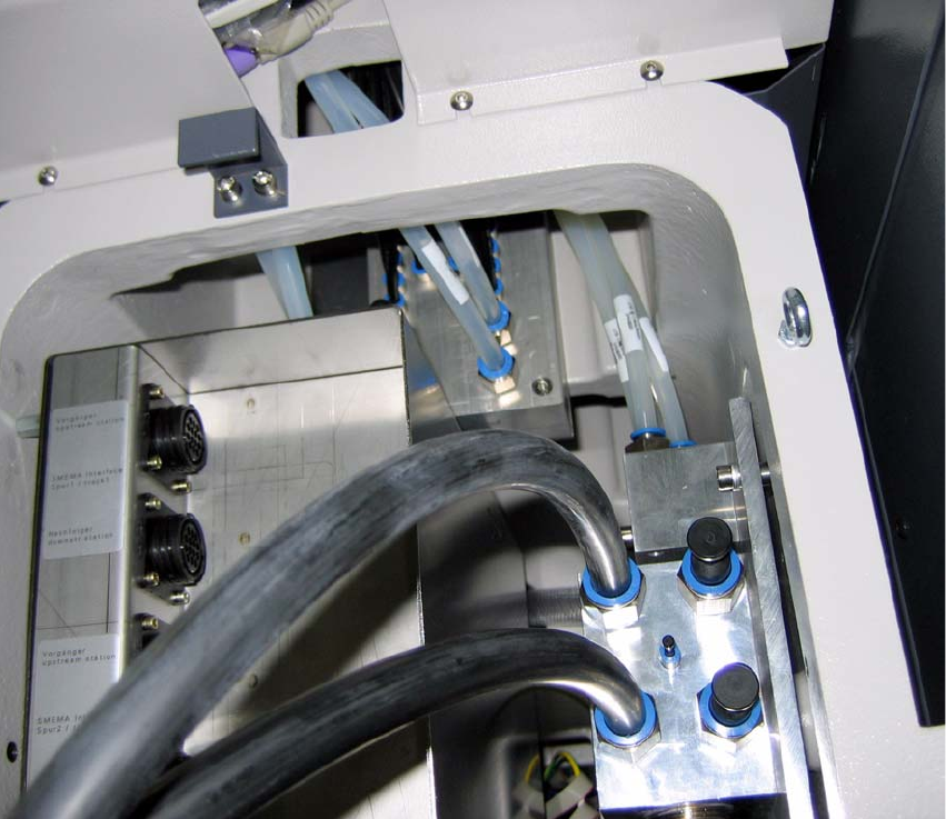
Fig. 2.7.7 Fasten vacuum distributor block
: Fasten the vacuum distributor block to the plate with the two screws (00845068-, DIN912,
M6x70-8.8).
2
Assembly Instructions SIPLACE Vacuum Pump
Ausgabe 07/2006
78
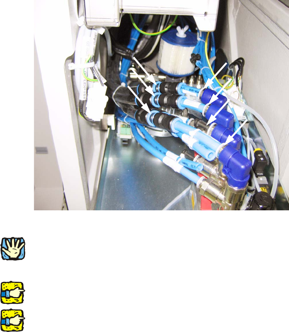
Fig. 2.7.8 Pneumatic unit with pressure connectors (connectors at starting point). Minor visual differences in the
pneumatic unit can occur here due to different versions of the pneumatic unit.
2
A portal with Twin Head cannot be retrofitted. Leave the portal hoses for that portal connected to
the pneumatic unit.
: Pull out the pneumatic unit.
2
As you can see here, this placement machine is operated with 3 portals (for a compressed air
connection there is a sealing plug instead of a pressure hose).
2
If you ever have to retrofit for compressed air, you must reconnect the hoses according to their
labelling (see Fig. 2.7.8).
: Press the blue rings and remove the reducers between the pneumatic unit (at the top
connections) and portal hose (keep the reducers for later retrofitting to, e.g., Twin Head).
: Press sealing plugs (03015210-, plug QSC-12H) into the pneumatic unit’s open angled plug-
and-socket connector (see Fig. 2.7.10).
Portal 1
Portal 4
Portal 3
Portal 2
Reducers
Assembly Instructions SIPLACE Vacuum Pump
Ausgabe 07/2006
79
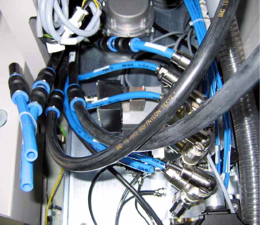
Fig. 2.7.9 VVacuum hoses from the vacuum distributor block to the portal hoses
(example is for placement machine with 2 portals)
: Plug the (black) vacuum hoses into the newly empty plug-and-socket connectors (see Fig.
2.7.8 and Fig. 2.7.10).