00195089-0102_AI_Vakuumpumpe_X-Serie_60X_DE+EN.pdf - 第90页
Assembly Instructions SIPLACE Vacuum Pump Ausgabe 07/2006 86 2.8.1 Mounting Fig. 2.8.5 Distributor placement head in Portal 2+4 (star ting position) 2 2 Bef ore any work is perf ormed the machine – after being pr operly …
Assembly Instructions SIPLACE Vacuum Pump
Ausgabe 07/2006
85
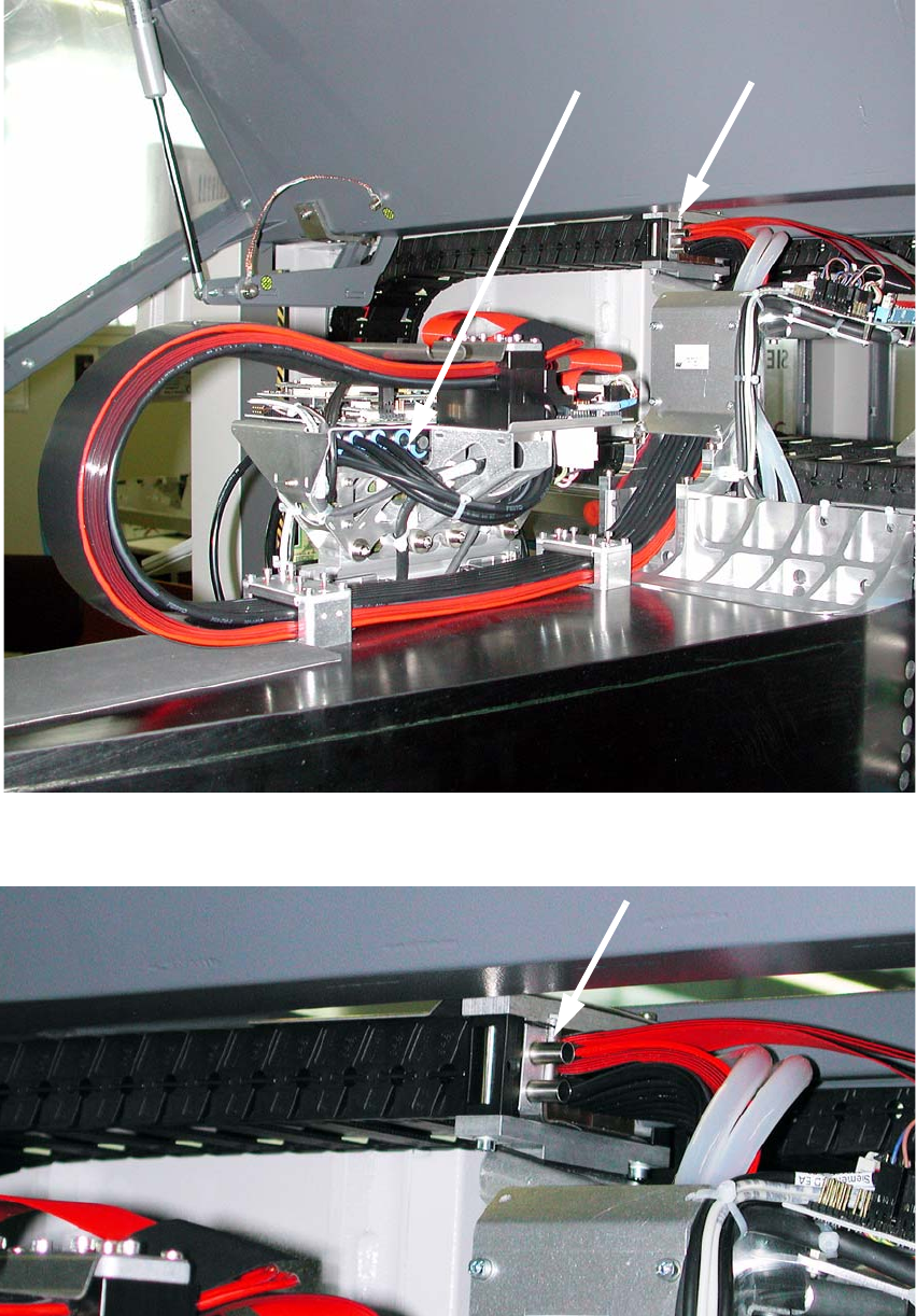
Fig. 2.8.3 Joints for vacuum on Portal 2+4 (starting position)
Fig. 2.8.4 Hose connection cable drag chain for Portal 2+4
Assembly Instructions SIPLACE Vacuum Pump
Ausgabe 07/2006
86
2.8.1 Mounting
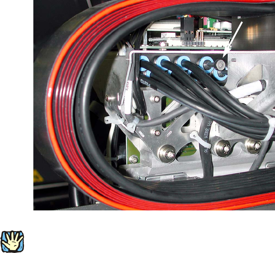
Fig. 2.8.5 Distributor placement head in Portal 2+4 (starting position)
2
2
Before any work is performed the machine – after being properly shut down – must be turned off
at the main switch and separated from the power system. Thereafter the compressed air supply
must also be turned off at the compressed air unit’s main valve in the machine stand. The air
supply must then be ventilated by activating the needle valve on the compressed air unit.
: Re
move both sealing plugs from the “distributor p
lacement head vacuum” at both portals with
the release tool for Q8 (see Fig. 2.8.6)
Assembly Instructions SIPLACE Vacuum Pump
Ausgabe 07/2006
87
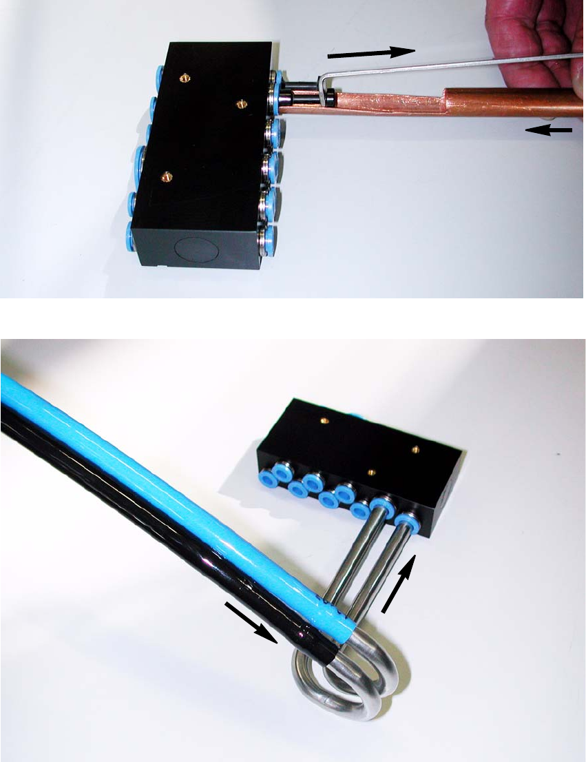
Fig. 2.8.6 Release tool for connections which are difficult to reach
Fig. 2.8.7 Distributor placement head (removed to better depict it)
: Plug the vacuum hoses into the vacuum pipes “vacuum connection 1 +2” as shown in Fig.
2.8.7.
: Plug the two pipes into the “distributor placement head vacuum” (Fig. 2.8.7).