Machine Control.pdf - 第5页
MACHINE CONTROL M36 MACHINE CONTROL ENCLOSURE Chapter Issue 3 Jan 08 Technical Reference Manu al 7.5 NextMove ES Card CAUTION ANTI-ST ATIC HANDLING. STANDARD PRECAUTIONS MUST BE ADHERED TO WHEN HANDLING ELECTR ONIC CARDS…
MACHINE CONTROL
M36 MACHINE CONTROL ENCLOSURE
7.4 Technical Reference Manual Chapter Issue 3 Jan 08
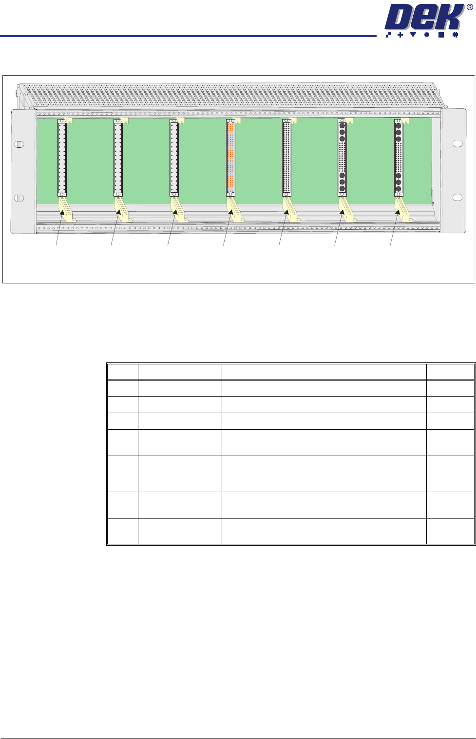
M36 Card Locations
Card Placement CAUTION
ANTI-STATIC HANDLING.
Standard precautions must be adhered to when
handling electronic cards and configuring and inserting into the enclo-
sures.
Slot X1 Slot X2 Slot X3 Slot X4 Slot X5 Slot X6 Slot X7
View on Front (front panel removed)
Slot Card Function Step/Axis
X1 Dual Stepper X Forward and X Rear Actuators Step 0,1
X2 Dual Stepper Front and Rear Squeegees Step 3,4
X3 Dual Stepper Y Actuator and Moving Rail Step 2,5
X4 NextMove Interface Opto-isolates 20 inputs and 8 outputs from the
NextMove ES card
X5 NextMove ES
(I/O Node1)
Motion control card providing 6 stepper and 2 servo
axes with real time I/O. Also acts as a CAN master
interfacing between the USB and CAN buses
X6 EF Servo Drive Camera X Linear Servo Motor
(linear drive machines only)
Axis 0
X7 EF Servo Drive Camera Y Linear Servo Motor
(linear drive machines only)
Axis 1
MACHINE CONTROL
M36 MACHINE CONTROL ENCLOSURE
Chapter Issue 3 Jan 08 Technical Reference Manual 7.5
NextMove ES Card
CAUTION
ANTI-STATIC HANDLING. STANDARD PRECAUTIONS MUST BE ADHERED TO
WHEN HANDLING ELECTRONIC CARDS AND CONFIGURING AND INSERTING
INTO THE ENCLOSURES.
The NextMove ES can control six stepper motor axes via stepper drive cards
and provides 4 analogue outputs, 2 analogue inputs, 20 digital inputs (interfaced
through the NextMove Interface card) and 8 digital outputs (interfaced through
the NextMove Interface card). Two of the analogue outputs are used as
demand outputs to control linear motors for camera X and Camera Y (linear
drive machines only). The card also incorporates a CAN encoder/decoder
which connects to I/O Node boards and Servo/Stepper Nodes using a CAN Bus
network. The CAN Bus network allows for future expansion of the system
without the need for further NextMove cards.
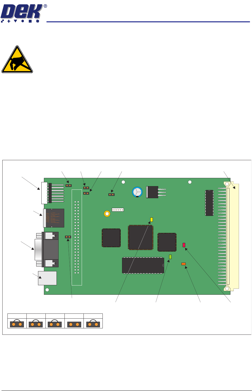
NextMove ES
Jumper Settings
The NextMove ES jumper settings are shown below:
Figure 7-1 NextMove ES Card
LED Indications The 7 segment LED display on the edge of the NextMove ES card indicates the
Node number (1) during normal operation. During initialisation, the display
indicates a dash (-) followed by a period (.).
JP1
JP2
JP3 JP4 JP57 Segment
LED Display
CAN Bus
Connector
M36SK35
Not Used
USB
Connector
M36SK28
96 Pin Edge Connector
JP3
JP2
JP1
JP4
JP5
D3
D4
D16
D20
MACHINE CONTROL
M36 MACHINE CONTROL ENCLOSURE
7.6 Technical Reference Manual Chapter Issue 3 Jan 08
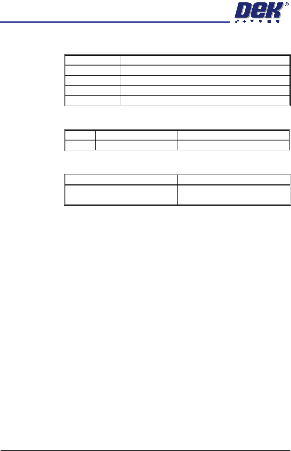
There are four surface mount LEDs on the board which are detailed in the table
below, NextMove ES Card figure refers:
Inputs The table below details the 2 analogue inputs:
Outputs The table below details the 4 analogue outputs:
LED Colour Normal Operation Purpose
D3 Yellow Off Indicates that the FPGA is being initialised
D4 Red Off Indicates that the card is in hardware reset
D16 Green Flashing Flashes at 0.5Hz to indicate firmware heartbeat
D20 Orange On Toggles on with reception of comms packet
Input Function Input Function
AIN0 USC Solvent Level AIN1 Spare
Output Function Output Function
AOUT0 Camera X (linear drive only) AOUT2 Spare
AOUT1 Camera Y (linear drive only) AOUT3 Temperature Output to TCM