00191369-02.pdf - 第108页
3 Introduction and Basic Concepts User Manual HS-50 3.2 Principles of the Graphic User I nterface Software Version SR.501.xx 12/99 Issue US 108 t I I t 3 Continue processi ng 3 This icon is dis playe d after " S top…
User Manual HS-50 3 Introduction and Basic Concepts
Software Version SR.501.xx 12/99 Issue US 3.2 Principles of the Graphic User Interface
107
t IIt
3.2.2.1 Icons in the Working or Display Area
In main view, certain operating statuses (processing, error etc.) are indicated by different icons or
by changes in the color of the corresponding graphic in the display area. 3
Meaning of the Icons for the Individual Operating Statuses 3
Machine power-up and reference run 3
The user interface cannot be operated while this icon is displayed. The software is being loaded.
Then the status field displays the status "Waiting for reference run" and the action "Press start
key". 3
Å Press the start key. The reference run is then performed.
The machine is ready to perform assembly operations. The following icon is displayed.
3
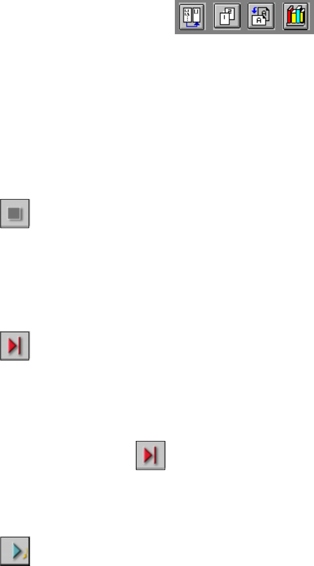
Stop processing PCB 3
When you click this icon, the current assembly operation is stopped.
Assembly of the PCBs located on the processing conveyors is completed and they are then trans-
ported to the intermediate or output conveyor of the associated conveyor track. No PCBs are
transported into the machine. 3
3
Å Click the icon .
The icon changes to the icon presented below. This continues to be displayed until assembly
of the current PCBs has been completed and these have been transported into the intermedi-
ate or output conveyor, i.e. until the processing conveyors have been emptied.
3
After "Stop processing PCB" while processing conveyors are emptied 3
(The triangle in the icon is continuously circled by a small yellow arrow.)
Once the processing areas have been emptied, the following icon is displayed. 3
3 Introduction and Basic Concepts User Manual HS-50
3.2 Principles of the Graphic User Interface Software Version SR.501.xx 12/99 Issue US
108
t IIt
3
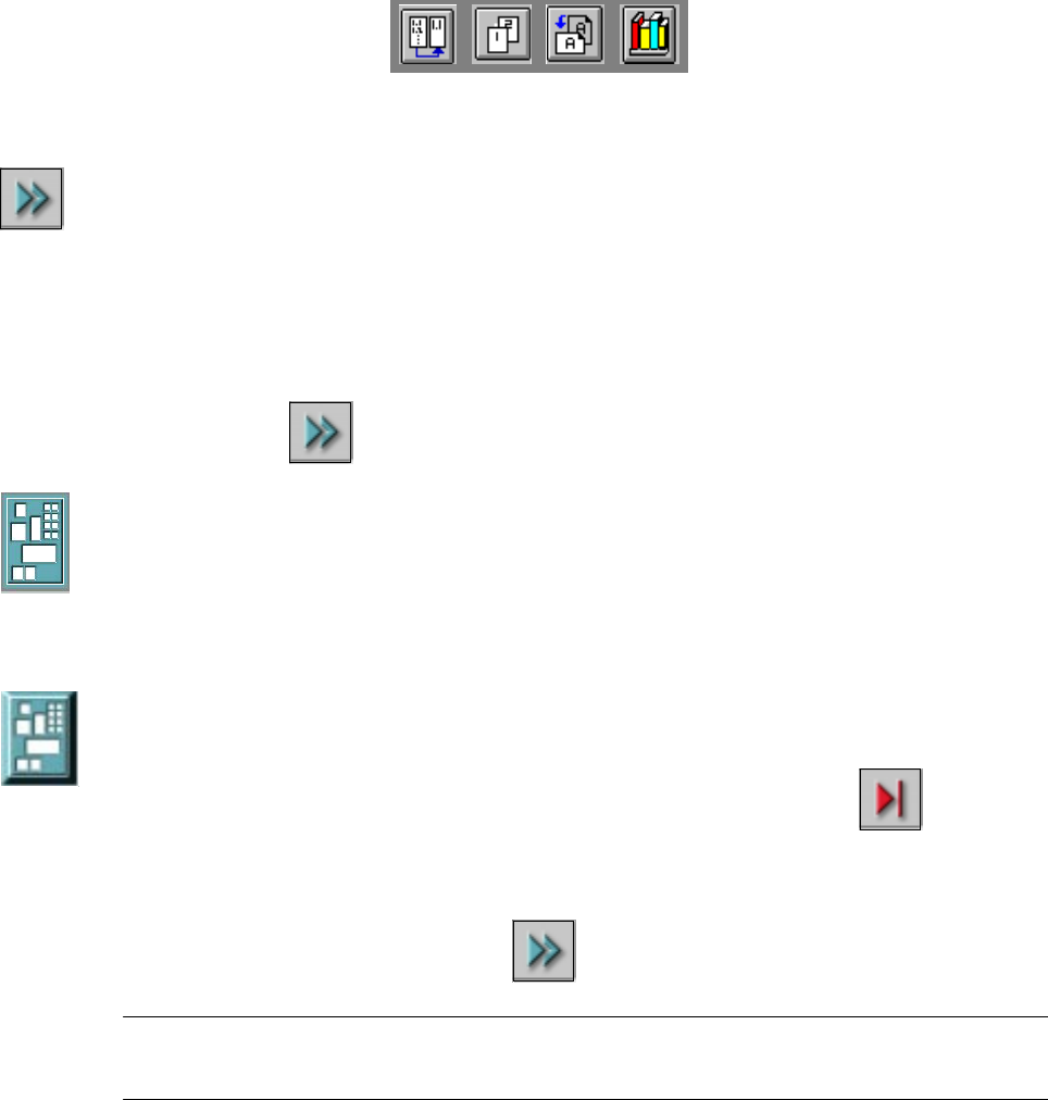
Continue processing 3
This icon is displayed after "Stop processing PCB" or after a machine stop.
(The triangles in the icon move continuously from left to right.)
Click this icon to continue the interrupted operation once the error has been successfully elimi-
nated. 3
3
Å Click the icon .
Processing is now continued.
3
Processing PCB 3
The PCB has been taken up be the system and is being processed. The PCB icon is displayed in
blue-green. 3
Processing of PCB stopped 3
If processing of the PCB has been interrupted using "Stop processing PCB"" or has been
interrupted after a fatal error or because the Stop button has been pressed, the PCB icon is again
displayed in blue-green but now has contoured edges.
3
You can continue processing by clicking
or abort it by clicking the PCB icon. 3
NOTE
The procedure used to abort processing is described below. 3
User Manual HS-50 3 Introduction and Basic Concepts
Software Version SR.501.xx 12/99 Issue US 3.2 Principles of the Graphic User Interface
109
t IIt
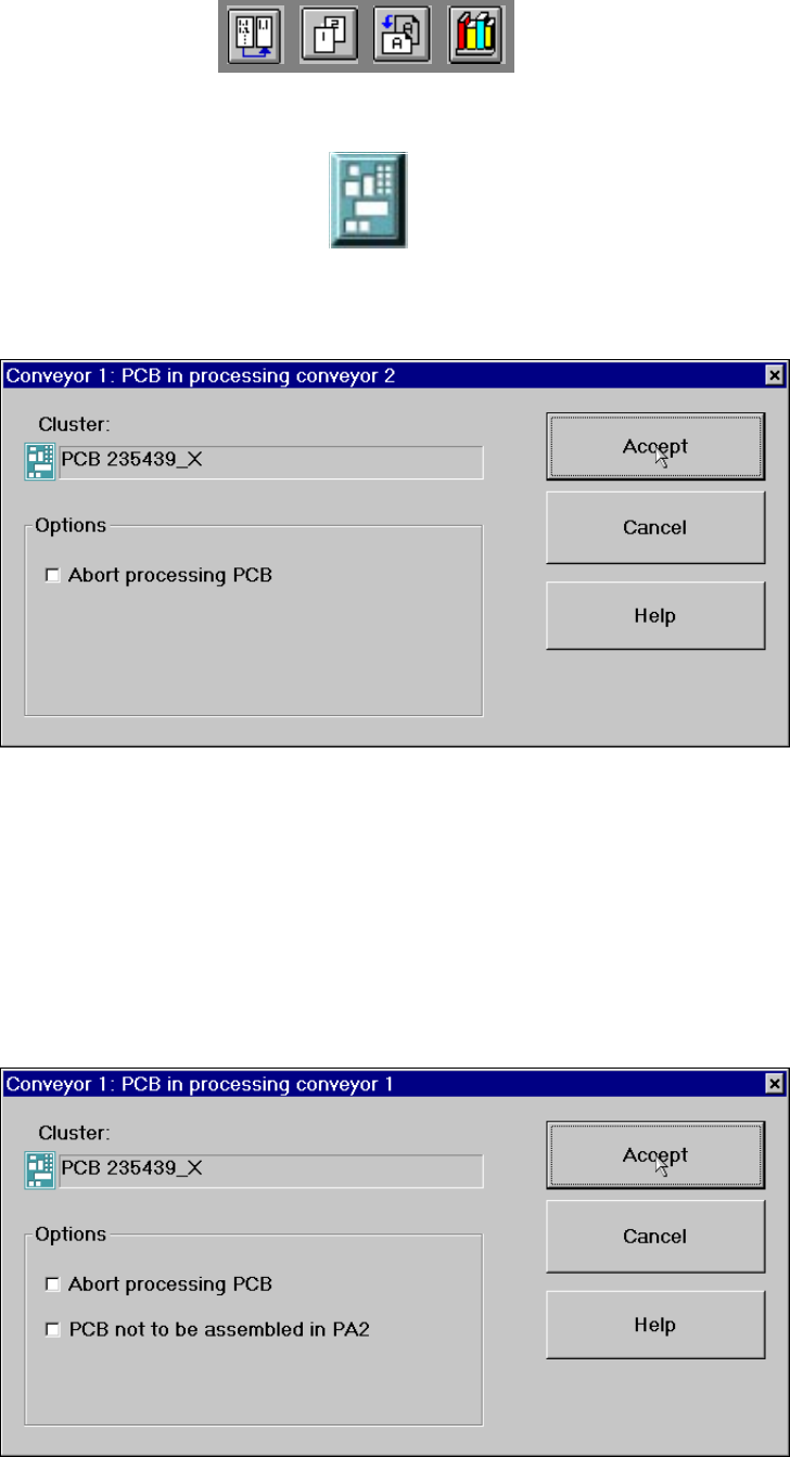
Abort processing 3
3
Å Click the corresponding PCB icon .
If the PCB is located on processing conveyor 2, the following dialog box is opened.
3
Å Click the checkbox "Abort processing PCB".
Å Click the Accept button.
Processing of the PCB is aborted.
The incompletely assembled PCB is transported to the output conveyor and the operator is re-
quested to remove it by hand.
If the PCB is located on processing conveyor 1, the following dialog box is opened. 3
3
3