00191369-02.pdf - 第114页
3 Introduction and Basic Concepts User Manual HS-50 3.3 User Interface - Views and Menus Software Version S R.501.xx 12 /99 Issue US 114 t I I t 3.3 Use r Interface - Views and Menus 3.3.1 V iews T o per form a part icul…
User Manual HS-50 3 Introduction and Basic Concepts
Software Version SR.501.xx 12/99 Issue US 3.2 Principles of the Graphic User Interface
113
t IIt
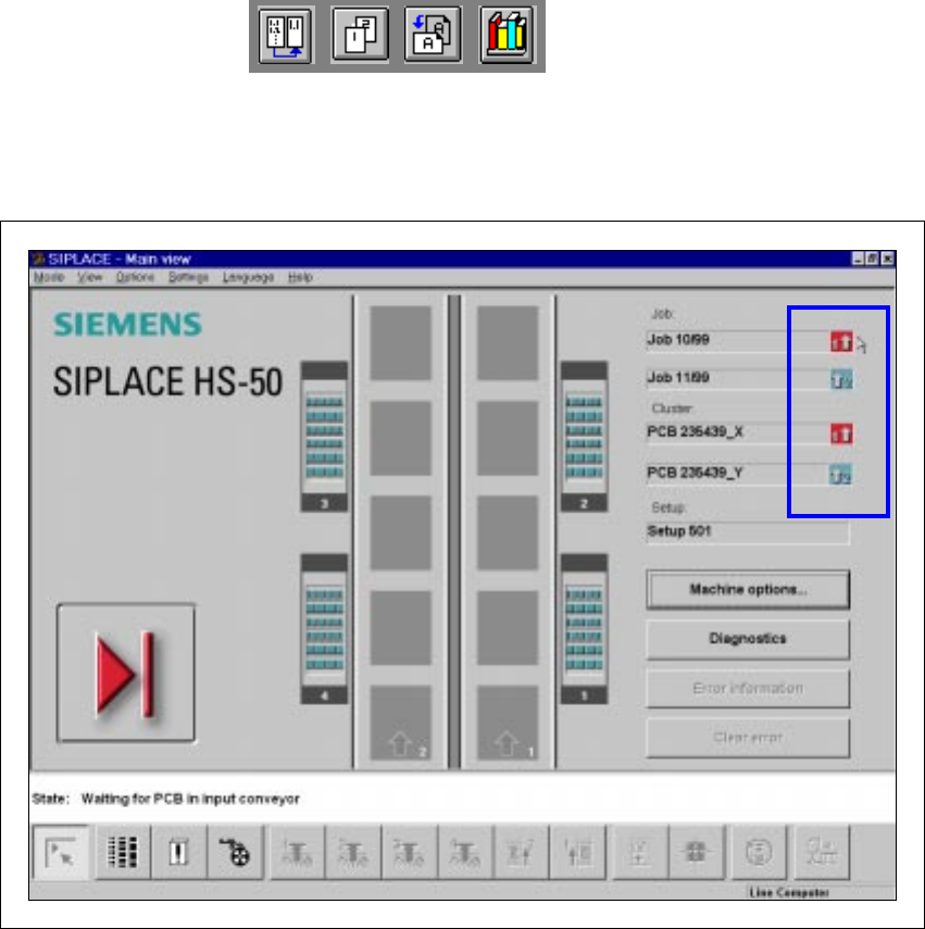
3.2.2.3 Status display for the conveyor interface
3
Fig. 3.2 - 3 Status display for the conveyor interface
The cluster and job name icons indicate the status of the conveyor interface. The icon is 3
– grayed out during the placement system start-up phase,
– green when the conveyor interface is enabled and
– red when the conveyor interface is blocked.
For example, the conveyor interface is disabled when a job is interrupted by the line computer,
processing is paused or a machine stoppage has occurred. 3
3
3 Introduction and Basic Concepts User Manual HS-50
3.3 User Interface - Views and Menus Software Version SR.501.xx 12/99 Issue US
114
t IIt
3.3 User Interface - Views and Menus
3.3.1 Views
To perform a particular operation at a particular moment via the user interface, you may need to
switch this to a different view. You can do this by clicking the appropriate toolbar button (see sec-
tion 3.2.2.2
) or by selecting the corresponding menu item in the "View" menu (see section 3.3.2.2). 3
NOTE
For a description of the functions available in the various views, refer to the chapters which explain
the procedures applicable to the operations to be performed (e.g. "Refilling an Empty Track With
"Refill track"", Chapter 4.1.2.3). 3
3.3.2 Menus
3.3.2.1 "Mode" Menu
The complete set of functions present in the "Mode" menu is only available in the main view.
In the views "Setup ...", "Errors..." and "Feeders" and their sub-views, only the menu items "Stop
processing PCB" and "Processing PCB" are available. In the other views, the "Mode" menu is not
displayed. 3
NOTE
For a detailed description of the menu items "Stop processing PCB", "Processing PCB" and "Con-
tinue processing", refer to section 3.2.2.1
since these functions are usually activated via the cor-
responding icons in the working area. 3
3
Processing PCB 3
Assembly of the PCBs is started or continued if previously interrupted. 3
Å Click the menu item Processing PCB (or the corresponding icon).
3
3
3
3
3

User Manual HS-50 3 Introduction and Basic Concepts
Software Version SR.501.xx 12/99 Issue US 3.3 User Interface - Views and Menus
115
t IIt
3
Stop processing PCB 3
The current PCB assembly process is stopped. 3
Å Click the menu item Stop processing PCB (or the corresponding icon)
Abort processing 3
This function allows you to abort certain operating steps such as feeder position recognition or
nozzle changes in the event of a machine stoppage (fatal error, Stop button pressed) 3
Å Click the menu item Abort processing.
The current operation is aborted when you confirm the action in the displayed dialog box.
Continue processing 3
The preceding assembly process, interrupted for example because of an error, is continued once
the fault has been eliminated. 3
Å Click the menu item Continue processing (or the corresponding icon).
Switch to MIS 3
This menu function cannot be executed in the current software version. 3
Switch to SIPLACE Pro 3
This menu function cannot be executed in the current software version. 3
Switch to operating system ... 3
You use this menu item to switch to the Windows operating system after entering your password.
From here, you can then subsequently return to the SIPLACE user interface. 3
NOTE
This menu option is not available at the "Operator" access level. 3
Å Click the menu item Switch to operating system ...
The Windows user interface is displayed and the SC software continues to run in the back-
ground.