00191369-02.pdf - 第174页
5 Single Functions User Manual HS -50 5.3 Single functions, Transport Software Version S R.501.xx 12 /99 Issue US 174 t I I t 5.3.1 "T ransport functions" screen The transp ort fu nctions are used for c hecking…
User Manual HS-50 5 Single Functions
Software Version SR.501.xx 12/99 Issue US 5.3 Single functions, Transport
173
t IIt
5.3 Single functions, Transport
NOTE
The travel functions of the X or Y-axis can only be carried out when the machine cover is closed.
To execute this function, press the start button.
As a rule, the gantries only travel slowly. The revolver head is set to travel slowly. 5
Å On the tool bar in the main view, click the symbol which represents the transport you want to
test the functions of (or select the corresponding menu item from the "View" menu, e.g. "Trans-
port 1" for Transport 1).
NOTE
When dual transport is installed and available in the machine options, the single functions
can be called for either the right-hand transport (Transport 1) or the left-hand transport
(Transport 2). The functions are identical for both right and left. The symbols used to call the
single functions are marked with the number which corresponds to the transport side.
Example for Transport 1 (= right-hand transport or single transport). 5
The user interface is switched to the "Transport functions" screen of the selected transport (see
Fig. 5.3 - 1
). 5
5
5 Single Functions User Manual HS-50
5.3 Single functions, Transport Software Version SR.501.xx 12/99 Issue US
174
t IIt
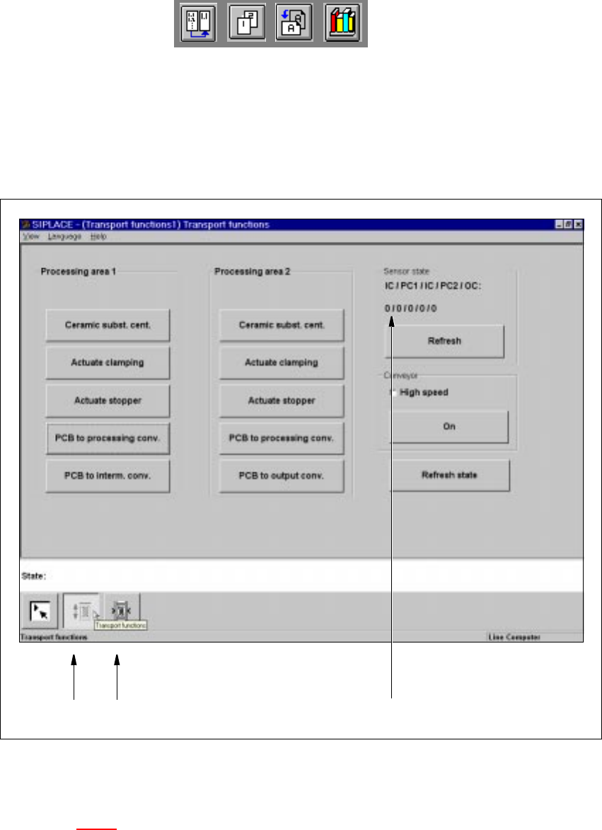
5.3.1 "Transport functions" screen
The transport functions are used for checking and adjusting the functional modules of the board
conveying systems. 5
5
Fig. 5.3 - 1 "Transport functions" screen
Key to Fig. 5.3 - 1
(1) Functions for the board conveying systems
(2) Functions for adjusting the transport conveyor width
(3) Functions to display state of the ultrasonic sensors
5
5
12
3
User Manual HS-50 5 Single Functions
Software Version SR.501.xx 12/99 Issue US 5.3 Single functions, Transport
175
t IIt
5.3.1.1 Functions
Ceramic subst. cent. 5
NOTE
The ceramic substrate centering function can only be activated if the "Ceramic substrate centering"
option is installed and entered in the machine options. 5
This function can be found in both "Processing area 1" and "Processing area 2" and is used to
check the centering (clamping) of ceramic substrate for each of the processing conveyors.
Å Click the PCB to processing conv. button in "Processing area 1".
The ceramic substrate is moved to processing conveyor 1.
Å Click the Ceramic subst. cent. button in "Processing area 1".
The ceramic sustrate is centered (clamped).
Å Click the Ceramic subst. cent. button again.
The centering is released again.
Å Click the PCB to processing conv. in "Processing area 2".
The ceramic substrate is moved to processing conveyor 2.
Å Click the Ceramic subst. cent. button in "Processing area 2".
The ceramic sustrate is centered (clamped).
Å Click the Ceramic subst. cent. button again.
The centering is released again.
Actuate clamping 5
This function is available for both "Processing area 1" and "Processing area 2" and can be used to
check board clamping for the corresponding processing conveyors. 5
Å Use the PCB to processing conv. function in "Processing area 1" to move the board to
processing conveyor 1.
Å Click the Actuate clamping button in "Processing area 1".
The board is clamped to processing conveyor 1.
Å Click the Actuate clamping button again.
The clamping is released again.
Å Use the PCB to processing conv. function in "Processing area 2" to move the board to
processing conveyor 2 and check the board clamping for this area as described above.