00191369-02.pdf - 第181页
User Manual HS-50 6 Vision functions Software Version S R.501.xx 12/99 Issue US 6.1 The vision systems on the placement system 181 t I I t 6 V ision functions 6.1 The vision systems on the placem ent system The quality r…

5 Single Functions User Manual HS-50
5.3 Single functions, Transport Software Version SR.501.xx 12/99 Issue US
180
t IIt
5.3.2.1 General comments
The "PCB conveyor width" screen makes available all functions necessary to adjust the width of
the conveyor.
It may be necessary to change the width of the conveyor, for example, for maintenance work or
when introducing a board with new dimensions. 5
The conveyor can be adjusted to suit the width of the board.
Incremental width adjustments are made by clicking the buttons "Larger" or "Smaller" (see section
5.3.2.2
).
Width adjustments can be made in large increments (increment size = 1 mm) or in smaller steps (in-
crement size = 0,1 mm). This can be controlled by activating or deactivating the "High speed" check
box in the "Width adjustment" area (see section 5.3.2.2
). 5
5
5.3.2.2 Functions
Measure width 5
This function can be used to measure the current width of the conveyor. The result is shown and
saved.
Å Click the Measure width button.
The measured width is displayed above the button.
5
Incremental adjustment
Å Activate the "High speed" check box to adjust the conveyor width in large increments.
Deactivate the check box if you want to adjust the conveyor width in smaller steps.
5
Conveyor width adjustment
Larger 5
Å Click the Larger button to increase the width of the conveyor.
Each time you click the button the width is increased by the increment size set using the
"High speed" check box.
Smaller 5
Å Click the Smaller button to reduce the width of the conveyor.
Each time you click the button the width is reduced by the increment size set using the
"High speed" check box.
5
User Manual HS-50 6 Vision functions
Software Version SR.501.xx 12/99 Issue US 6.1 The vision systems on the placement system
181
t IIt
6 Vision functions
6.1 The vision systems on the placement system
The quality requirements concerning the accuracy of automatic placement systems are constantly
rising, for several reasons: 6
– continuing miniaturization of components,
– increasing lead connection density,
– increasing complexity of PCBs and
– increasing component density.
6
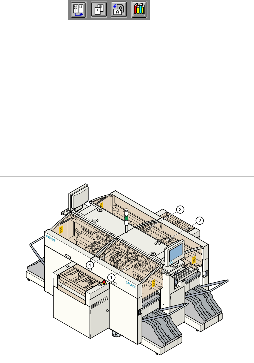
Fig. 6.1 - 1 Position of the gantries and DLM1 revolver heads
(1) Gantry 1 with DLM1 revolver head and component and PCB vision system
(2) Gantry 2 with DLM1 revolver head and component and PCB vision system
(3) Gantry 3 with DLM1 revolver head and component and PCB vision system
(4) Gantry 4 with DLM1 revolver head and component and PCB vision system

6 Vision functions User Manual HS-50
6.1 The vision systems on the placement system Software Version SR.501.xx 12/99 Issue US
182
t IIt
To help meet these requirements, high-precision mechanical components are combined with op-
tical centering and detection systems (known as vision systems) for components and PCBs. 6
The placement system has four gantries (see Fig. 6.1 - 1
). On each of these gantries there is a
DLM1 revolver head with a separate component camera system (see Fig. 6.1 - 2
). A PCB camera
system is mounted on the underside of the head mount of each gantry (see Fig. 6.1 - 3
). 6
Vision analysis units 6
The two vision analysis units plug into the control unit (see items 1 and 2 in Fig. 6.1 - 4). The com-
ponent and PCB cameras, combined with the vision analysis units form the vision system. 6
The electrical image signals from the component and PCB camera systems are sent to the vision
analysis units (see items 1 and 2 in Fig. 6.1 - 4
), where the measured values are compared with
the artificial values from the component description or PCB fiducials. The result is used to calcu-
late the correction factors for the individual placement positions. 6
The components are also identified by their package forms. The component is not placed if the
artificial model and the package form measurement do not correspond. 6
The PCB vision system can also be used to detect the position of the feeder modules. Fiducials
on the feeder modules are used to calculate the position deviation of individual feeder modules.
The pick-up reliability can be greatly increased in this way, even for tiny components. 6
6.1.1 Component camera system on the revolver head
The component camera system (see item 2 in Fig. 6.1 - 2) essentially consists of the following
modules: 6
– Lens system
– CCD chip for creating an electronic image of the component
– CCD camera amplifier
– Three illumination planes - flat, medium and steep - for optimum lighting of a wide range of
component shapes
– "Illumination control" board for setting the intensity of the individual illumination planes