00191369-02.pdf - 第192页
6 Vision functions User M anual HS-50 6.2 PCB vision system Software Version SR.501.xx 12/99 Is sue US 192 t I I t file or tra nsferred from the CAD file to the NU file. In this way , the coordi nates a nd fiduci al st r…
User Manual HS-50 6 Vision functions
Software Version SR.501.xx 12/99 Issue US 6.2 PCB vision system
191
t IIt
The template window is moved over the search area in moxel steps. The gray scale values of each
moxel of the reference fiducial are calculated at this time. This reduced data structure will contain
enough information on the coarse structure and position of the reference fiducial. 6
NOTE 6
The search window should be as small as possible in order to keep the speed of searching high.
On the other hand the window should be large enough to allow the fiducial to be identified with-
out ambiguity.
The 1-D pattern search procedure is used for precisely determining the pattern and position of the
fiducial. The fiducial image is broken up into rows and columns and the gray scale values in each
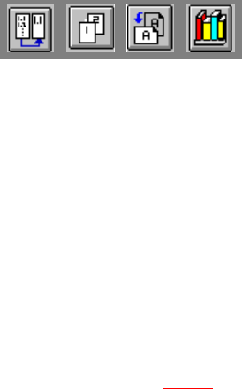
row and column added up. The next diagram illustrates this process using a double cross. 6
6
Fig. 6.2 - 2 Row and column profile of a double cross
Key to Fig. 6.2 - 2
(1) Fiducial
(2) Sum of the grey scale values in one column: column profile
(3) Sum of the grey scale values in one row: row profile
6
– The position of the fiducial is precisely determined from the horizontal and vertical profiles.
After teaching, the fiducial structure parameters obtained are saved to the line computer.
– The saved pattern is now tested. The gantry moves the PCB camera over the board to all 4
corners of the search area (worst case). During this test the vision system must re-identify the
fiducial four times.
– Finally, the coordinates of each individual fiducial (at least two) are manually added to the NU
1
2
3
6 Vision functions User Manual HS-50
6.2 PCB vision system Software Version SR.501.xx 12/99 Issue US
192
t IIt
file or transferred from the CAD file to the NU file. In this way, the coordinates and fiducial struc-
ture parameters for the board are defined as a pattern in the system.
– During the placement process, the fiducial will be determined once again using the 1-D and
2-D image processing methods described above. The template window is moved moxel by
moxel over the search area searching for the best possible agreement of the gray scale values
of the reference and board search fiducials (correlation procedure). Maximum correlation is at-
tained when the reference and search fiducials agree.
– Once the fiducial has been found, the 1-D pattern search process begins. The precise shape
and coordinates of the fiducial are determined in each case by applying the correlation proce-
dure to the column and row profiles (see Fig. 6.2 - 2
). From the coordinates obtained in this
way, the location, skew and shear of the board are determined.
Reject fiducials (= ink dots) are also detected and evaluated using the methods described
above.
6.2.5 Criteria for Creating Fiducials
Basically the same criteria apply to both fiducials and reject fiducials (ink dots): uniqueness of fi-
ducial shapes and readily detectable structures which stand out from their surroundings. 6
Use existing structures as fiducials 6
Instead of fiducials, you can also use uniquely identifiable structures within the PCB layout. It
should, however, be remembered that solder stop lacquer is frequently accompanied by a loss in
contrast. 6
Location of the fiducials 6
Position the fiducial where there are as few structures as possible and where the fiducial will stand
out well from its surroundings. Measuring outwards from the center of the fiducial, there should be
a clearance on each side equal to at least one fiducial size plus 1 mm. 6
Types of fiducials 6
There are 2 types of fiducials: 6
– Positive fiducials
The fiducial extends above the base material of the board.
– Negative fiducials
The fiducial is etched into the base material of the board.
User Manual HS-50 6 Vision functions
Software Version SR.501.xx 12/99 Issue US 6.2 PCB vision system
193
t IIt
Fiducial shape 6
Always choose a well-structured, distinct shape as fiducial shape: 6
Recommended fiducial shapes: 6
Rectangle, square or circle
Properties 6
– Low informational content (fiducials can easily be confused with test dots).
NOTE 6
Make sure that there are no similar structures in the fiducial search area. 6
– Low space requirements in the layout
– Very robust with respect to different tinning procedures (e.g. hot-tinning).
6
Recommended fiducial dimensions 6
– for square and rectangles: Side length 1.2 mm - 2.2 mm
– for the circle: Diameter 1.2 mm - 2.2 mm
Double cross and single cross 6
Properties of the double cross 6
– Higher informational content
– More space required in the layout
– Sensitivity with respect to high tin-coatings (bare copper is preferable)
– Poor fiducial quality may result in incorrect position recognition.
Properties of the simple cross 6
– The informational content is somewhat lower than with the double cross
– Less space required in the layout than with the double cross.
– Less sensitive to high tin-coatings than with the double cross.