00191369-02.pdf - 第199页
User Manual HS-50 6 Vision functions Software Version S R.501.xx 12/99 Issue US 6.3 Component Vision System 199 t I I t 6 Fig. 6.3 - 1 Regular component Key to Fig. 6.3 - 1 (1) Axi s of s ymmet ry 6 Criteria for irregula…

6 Vision functions User Manual HS-50
6.3 Component Vision System Software Version SR.501.xx 12/99 Issue US
198
t IIt
Component sizes: 0.5 mm x 0.5 mm to 18.7 mm x 18.7 mm 6
Range of recognizable components : TSOP, LCC, PLCC, QFP, SO series through SO28
basically all components with J and
gull-wing leads, µBGAs 6
Minimum lead pitch: 0.3 mm for the camera
0.5 mm for the machine 6
Minimum ball diameter with µBGAs: 250 µm 6
6.3.1.3 Description of Function
One segment of the 12x placement head picks up a component at star station 1. As the star ad-
vances, additional components are picked up. Once a componentz reaches star station 7 where
the component vision system is located, LED lights, as described earlier, illuminate the component
so that the CCD sensor can process the image. The lens will allow components with a height up
to 5 mm to be sharply focused and recognized by the camera’s CCD chip. 6
The digitally processed image is then transmitted to the vision analysis unit. Using the HALE pro-
cess, the analysis unit compares the image of the component with a synthetic model previously
generated in the GF editor (the package form editor). The parameters obtained through this pro-
cess yield information on positional deviations, lead condition and component identification. The
HALE process has proved to be highly resistant to interference factors such as unwanted reflec-
tions, diffused light influences , etc. and it is faster and more accurate than the matching method.
Once measurement has been completed, the star advances to station 9 where the segment ro-
tates the component into the correct orientation for placement. Finally, in star station 1, the com-
ponent is placed in its correct position on the board. 6
6.3.2 Criteria for Recognition of Components
Shape of the Components 6
Optical component centering allows both regular and irregular components to be centered. The
maximum number of leads, horizontally and vertically, is 99 in each case. 6
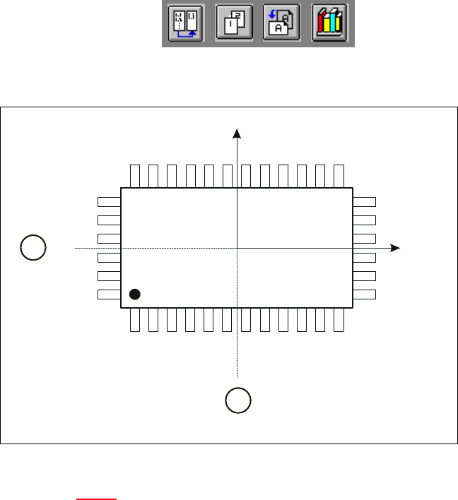
Criteria for regular components 6
Definition:
A component is deemed to be regular when it satisfies the following four conditions: 6
– rectangular package shapes (special case: square shape)
– only one lead type per side
– only one lead group per side
– opposite lead groups located symmetrically with respect to the two main axes
(X and Y axes).
User Manual HS-50 6 Vision functions
Software Version SR.501.xx 12/99 Issue US 6.3 Component Vision System
199
t IIt
6
Fig. 6.3 - 1 Regular component
Key to Fig. 6.3 - 1
(1) Axis of symmetry
6
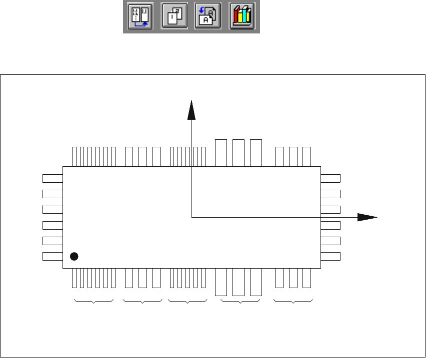
Criteria for irregular components 6
Definition:
A component is deemed to be irregular when it does not satisfy the conditions for regular compo-
nents. 6
Additional conditions for centering with the component vision system: 6
– In any one row up to 3 different lead types are permitted.
– In any one row up to 15 groups are permitted.
6
Y
X
Pin 1
1
1
6 Vision functions User Manual HS-50
6.3 Component Vision System Software Version SR.501.xx 12/99 Issue US
200
t IIt
6
Fig. 6.3 - 2 Example of irregular components
Pitch deviation 6
The pitch deviation (which is the distance from the center of one lead to the center of the next) can
be edited separately for each component in the GF editor. If this value is exceeded during the vi-
sion inspection, the component will not be centered and therefore not placed. 6
Limit values for quality measurement 6
Components exceeding the limit values for quality measurement will be rejected and, therefore,
not placed: 6
– Difference in the number of leads between the original and the model.
– Pitch deviation larger than the value in the GF file.
– Larger orthogonality error than specified in the GF file.
– Larger deviations of the external dimensions.
– Deviation of the central point greater than the permitted positional tolerance for pick-up.
X
Pin 1
Y
X
Pin 1
Type 1
Group 1
Type 2
Group 1
Type 1
Group 2
Type 3
Group 1
Type 2
Group 2