00191369-02.pdf - 第22页
1 Introduction User Manual HS-50 1.4 Revision index Software Version SR.501.xx 12/99 Issue U S 22 t I I t 1.4 Rev ision index 1 1.4.1 Revisions s ince 12/1 999 editi on 1 Instructions Software ve rsion Issue First dra ft…

User Manual HS-50 1 Introduction
Software Version SR.501.xx 12/99 Issue US 1.3 User classification
21
t IIt
1.3 User classification
The operating software is structured so that certain functions or menus can only by used or called
by appropriately trained personnel. There are three different classes of user: 1
– operators,
– line engineers and
– service engineers.
Access to each class may be password-protected. Chapters containing information for user
classes higher than "operator" contain a reference to the user class concerned in the footer. 1
Operators 1
The operator class consists of any person who has been trained in operation of the machine.
These people are authorized to use any functions associated with operating the machine and may
call up any menus needed to use the machine. 1
Line engineers 1
Line engineers have undergone special training and are authorized to carry out line engineer ac-
tivities, such as creating set-up configurations, determining vision parameters, etc. 1
Service engineers 1
This class is reserved for Siemens engineers, who are trained to carry out servicing work and to
upgrade and retrofit the placement system. 1
WARNING
A thorough knowledge of the relevant part of this User Manual is required before carrying out any
work on the machine. All work must be carried out by appropriately trained and qualified person-
nel. All warning, caution and danger notes MUST be observed. 1
PLEASE NOTE: The content of this User Manual is not part of or intended to modify a previous or
existing agreement, undertaking or legal relationship. Any undertakings entered into by Siemens
AG result from the purchase contract, which also contains complete and generally applicable
guarantees. Such contractual guarantee provisions are neither extended nor restricted by the in-
formation given in this User Manual. 1

1 Introduction User Manual HS-50
1.4 Revision index Software Version SR.501.xx 12/99 Issue US
22
t IIt
1.4 Revision index
1
1.4.1 Revisions since 12/1999 edition
1
Instructions Software version Issue
First draft HS-50 Provisional User Manual
5.01 09/98
Revision of HS-50 User Manual
5.01 01/99
Revision of HS-50 User Manual
5.01.03 12/99
New or modified Chapter / Section
SIPLACE on the World Wide Web (WWW)
1.1.3
Technical data - electrical ratings 1.7.2
Technical data - dimensions, weight 1.9.2
The placement system’s center of gravity 1.9.3
Power supply 1.10.5
Technical data - dual conveyor 1.15.3
Warning signs on the placement system 2.1.5
Safety instructions for changing the height of component tables 2.1.9
Energy state of the placement system after switching off at the main switch 2.5
Icons in the Working or Display Area 3.2.2.1
Status display for the conveyor interface 3.2.2.3
"Options" Menu 3.3.2.3
"Language" Menu 3.3.2.4
"Track errors location X" view 4.2.3
"Omit components" view 4.3.2
Program Transform 5 Option’ 6.5.5.2
Transform ... Option 6.6.4.12
Recommendations regarding the Optimum Sequence of Measurement Methods 6.6.4.15
‘Size’ measuring mode 6.6.4.16
'Row' measuring mode 6.6.4.17
‘Corner’ measuring mode 6.6.4.18
Shapes and possible measuring methods for rough (G) and fine centering (F) 6.7.3
3 x 8 mm S module 10.2.2
Asynchronous conveyor mode 11.3.4
Technical data for the dual conveyor 11.3.7
User Manual HS-50 1 Introduction
Software Version SR.501.xx 12/99 Issue US 1.5 Description of the machine
23
t IIt
1.5 Description of the machine
1.5.1 Functional description
The automatic placement system is a high-performance placement system with four gantry axis
systems. A PCB vision system and a star-shaped 12-segment revolver head are mounted on each
gantry. Revolver placement heads equipped with a component vision system pick up the compo-
nents from stationary feeder modules and insert them into the PCB clamped in the PCB con-
veyor. 1
1
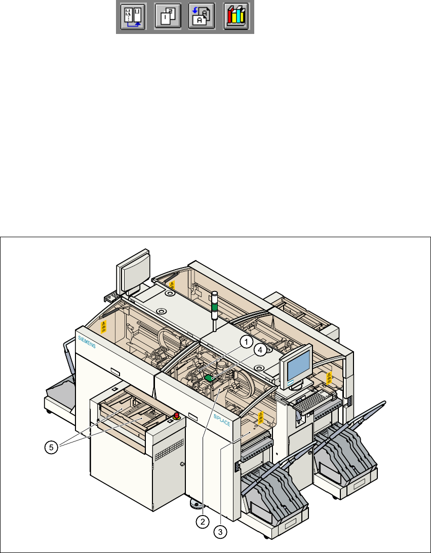
Fig. 1.5 - 1 Functional description of the placement system
(1)12-segment revolver head/DLM1 with component vision camera
(2)Gantry axis system with PCB vision camera
(3)Stationary component feeder
(4)Clamped printed circuit board (PCB)
(5)PCB conveyor (dual conveyor option)
1