00191369-02.pdf - 第23页
User Manual HS-50 1 Introduction Software Vers ion SR.501.xx 12/99 Issue US 1.5 Description of the machine 23 t I I t 1.5 Description of the machine 1.5.1 Functional description The automati c pla cement s ystem is a hi …

1 Introduction User Manual HS-50
1.4 Revision index Software Version SR.501.xx 12/99 Issue US
22
t IIt
1.4 Revision index
1
1.4.1 Revisions since 12/1999 edition
1
Instructions Software version Issue
First draft HS-50 Provisional User Manual
5.01 09/98
Revision of HS-50 User Manual
5.01 01/99
Revision of HS-50 User Manual
5.01.03 12/99
New or modified Chapter / Section
SIPLACE on the World Wide Web (WWW)
1.1.3
Technical data - electrical ratings 1.7.2
Technical data - dimensions, weight 1.9.2
The placement system’s center of gravity 1.9.3
Power supply 1.10.5
Technical data - dual conveyor 1.15.3
Warning signs on the placement system 2.1.5
Safety instructions for changing the height of component tables 2.1.9
Energy state of the placement system after switching off at the main switch 2.5
Icons in the Working or Display Area 3.2.2.1
Status display for the conveyor interface 3.2.2.3
"Options" Menu 3.3.2.3
"Language" Menu 3.3.2.4
"Track errors location X" view 4.2.3
"Omit components" view 4.3.2
Program Transform 5 Option’ 6.5.5.2
Transform ... Option 6.6.4.12
Recommendations regarding the Optimum Sequence of Measurement Methods 6.6.4.15
‘Size’ measuring mode 6.6.4.16
'Row' measuring mode 6.6.4.17
‘Corner’ measuring mode 6.6.4.18
Shapes and possible measuring methods for rough (G) and fine centering (F) 6.7.3
3 x 8 mm S module 10.2.2
Asynchronous conveyor mode 11.3.4
Technical data for the dual conveyor 11.3.7
User Manual HS-50 1 Introduction
Software Version SR.501.xx 12/99 Issue US 1.5 Description of the machine
23
t IIt
1.5 Description of the machine
1.5.1 Functional description
The automatic placement system is a high-performance placement system with four gantry axis
systems. A PCB vision system and a star-shaped 12-segment revolver head are mounted on each
gantry. Revolver placement heads equipped with a component vision system pick up the compo-
nents from stationary feeder modules and insert them into the PCB clamped in the PCB con-
veyor. 1
1
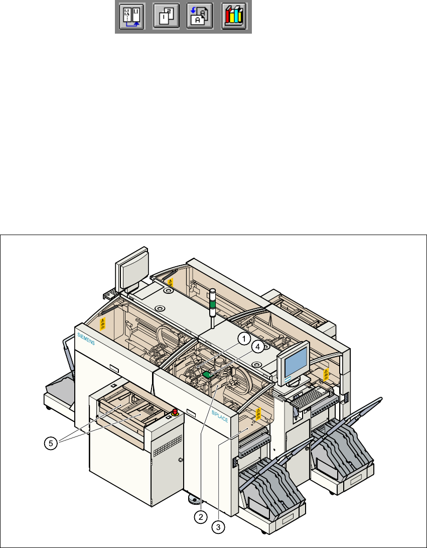
Fig. 1.5 - 1 Functional description of the placement system
(1)12-segment revolver head/DLM1 with component vision camera
(2)Gantry axis system with PCB vision camera
(3)Stationary component feeder
(4)Clamped printed circuit board (PCB)
(5)PCB conveyor (dual conveyor option)
1

1 Introduction User Manual HS-50
1.5 Description of the machine Software Version SR.501.xx 12/99 Issue US
24
t IIt
1
The concept behind the automatic placement system 1
– with its stationary feeder modules,
– PCBs that do not move during placement
– and positionable placement heads
has a number of significant benefits: 1
– For example, the flexible 12-segment revolver heads combined with automatic nozzle chang-
ers enable the nozzle configuration to be changed temporarily and automatically adapted to
receive different component sizes. You can also optimize the traversing paths and the place-
ment sequence.
– With stationary feeder modules, even the tiniest components are picked up reliably.
– The components cannot slip on the PCB during placement (as is often the case with moving
PCBs) since the PCB does not move.
– Sophisticated optical centering systems (vision systems) for components and PCBs also en-
sure high component positioning accuracy.
– Components can be topped up and tapes can be spliced without stopping the machine.
– Prepared component tables enable the placement system to be retooled without long stop-
pages.
1.5.2 Technical data - machine overview
Range of components From 0402 to PLCC44, SO32, DRAM
Maximum placement speed of the12-segment
revolver head/DLM1
50,000 components/hour
Cycle time at the revolver head 125 ms, regardless of the type of component
Accuracy
± 90 µm at 4 sigma
± 135 µm at 6 sigma
PCB format
50 x 50 mm to 368 x 460 mm
2" x 2" to 14.5" x 18"
Feeding capacity Up to 96 tracks, each with 8 mm tapes
Feeder modules Tapes, bulk-cases
Operating system Microsoft Windows NT / RMOS
Combination options Inline or stand-alone
Space required 7.5 m² / module