00191369-02.pdf - 第293页
User Manual HS-50 6 Vision functions Software Version S R.501.xx 12/99 Issue US 6.6 Test Comp onent 293 t I I t This menu is used to sel ect the 6 – int egrat ion dir ection, – the resolu tion i n the me asuring dire cti…
6 Vision functions User Manual HS-50
6.6 Test Component Software Version SR.501.xx 12/99 Issue US
292
t IIt
Method for calculating the rotation 6
Here you must specify the number of rotation windows in order to determine the angle: 6
– Automatic selection
The system selects the number of windows.
– SWIN method (Single Window)
Selects a single window. This method is suitable for small and complex components or com-
ponents with fluctuating dimensions.
– TWIN method (Two Windows)
Two windows are selected. This method is particularly suitable for rapid analysis, for PLCCs,
for example. However, this requires the structures to be investigated to lie in the center of the
window. If this is not the case, select just one window (SWIN method).
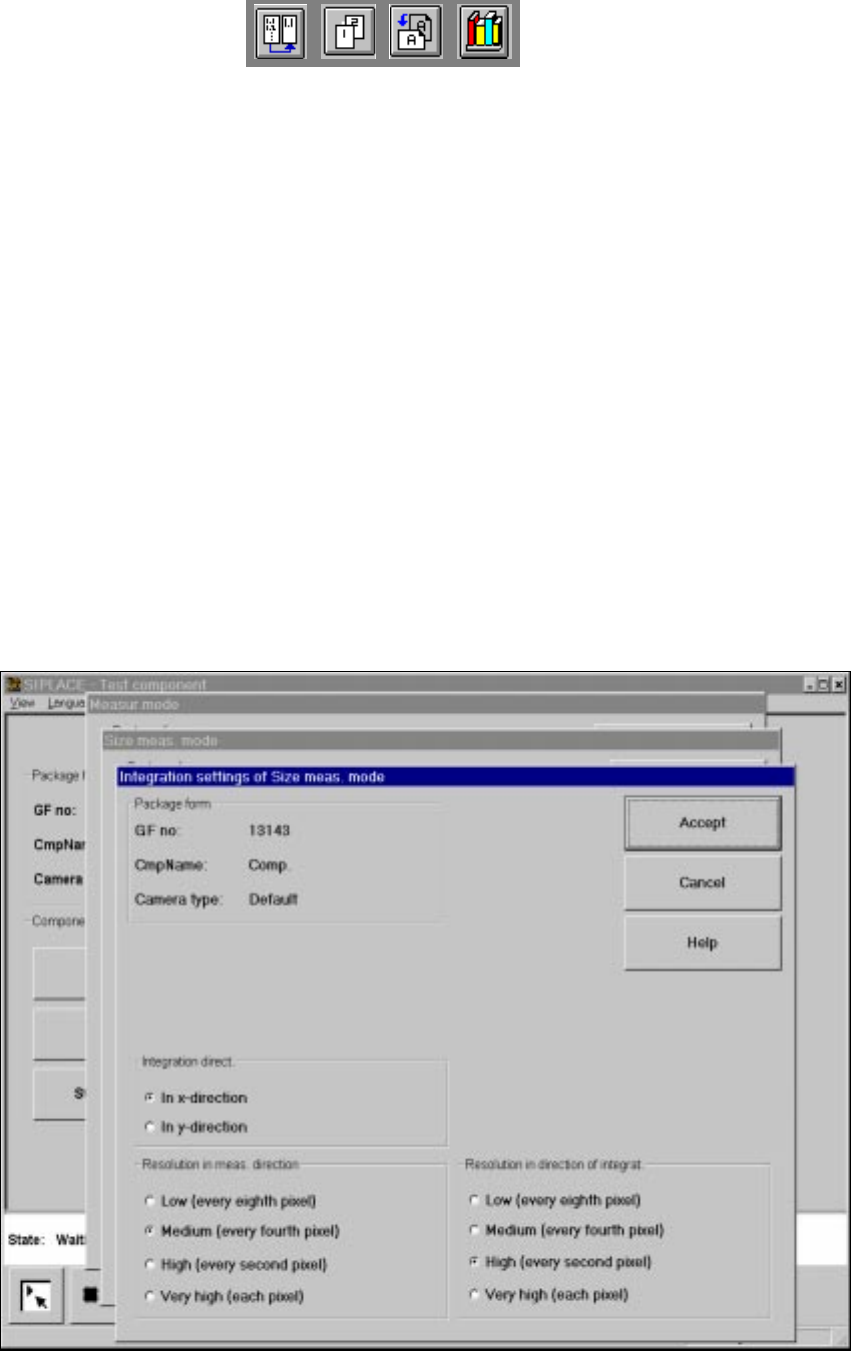
Integration settings 6
If you click on the 'Integration settings' field, the Integration settings of Size measuring mode
menu will appear on screen. 6
6
Fig. 6.6 - 36 Measuring mode option, Integration settings of Size measuring mode menu
User Manual HS-50 6 Vision functions
Software Version SR.501.xx 12/99 Issue US 6.6 Test Component
293
t IIt
This menu is used to select the 6
– integration direction,
– the resolution in the measuring direction and
– the resolution in the integration direction.
Integration direction 6
In order to determine the angle, select the integration direction towards either the X or Y axis of
the component. We recommend that you select the longer edge. 6
Resolution in the measuring direction 6
Select this resolution in order to optimize the measuring times at the revolver head. 6
Resolution in the integration direction 6
Select this resolution in order to optimize the measuring times at the revolver head. 6
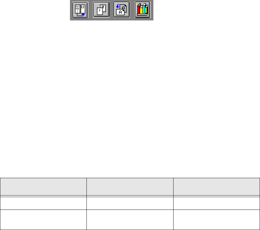
Resolution
in the measuring direction
Resolution
in the integration direction
Small components very high very high
Large components with another
measuring step to follow high medium
6 Vision functions User Manual HS-50
6.6 Test Component Software Version SR.501.xx 12/99 Issue US
294
t IIt
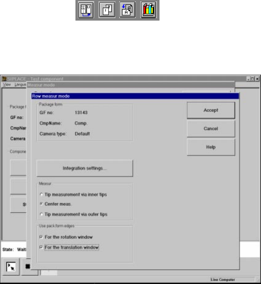
6.6.4.17 ’Row’ measuring mode
Click on the ‘Setting’ field in the Row measuring mode menu to call up the following menu: 6
6
Fig. 6.6 - 37 Measuring mode option, Row measuring mode menu
This menu is used to 6
– specify the lead measuring method.
– use the package form edges for the rotation windows and/or translation windows.
Measurement 6
If the inner lead tips are mapped better than the outer tips, for example, if a shiny lead is bent up-
wards slightly, you can select one of the following options: 6
– measuring the tips via the inner tips of the leads, for bases, for example
– center of the lead, center measurement, for PLCC, SOJ, for example
– measuring the tips via the outer tips of the leads, for QFP, SOT, SO, for example