00191369-02.pdf - 第294页
6 Vision functions User M anual HS-50 6.6 Test Component Software V ersion SR.501.xx 12/99 Issue U S 294 t I I t 6.6.4.17 ’ Row ’ measuring mode Click on the ‘Setti ng’ fi eld in th e Row mea suring mode menu to call up …
User Manual HS-50 6 Vision functions
Software Version SR.501.xx 12/99 Issue US 6.6 Test Component
293
t IIt
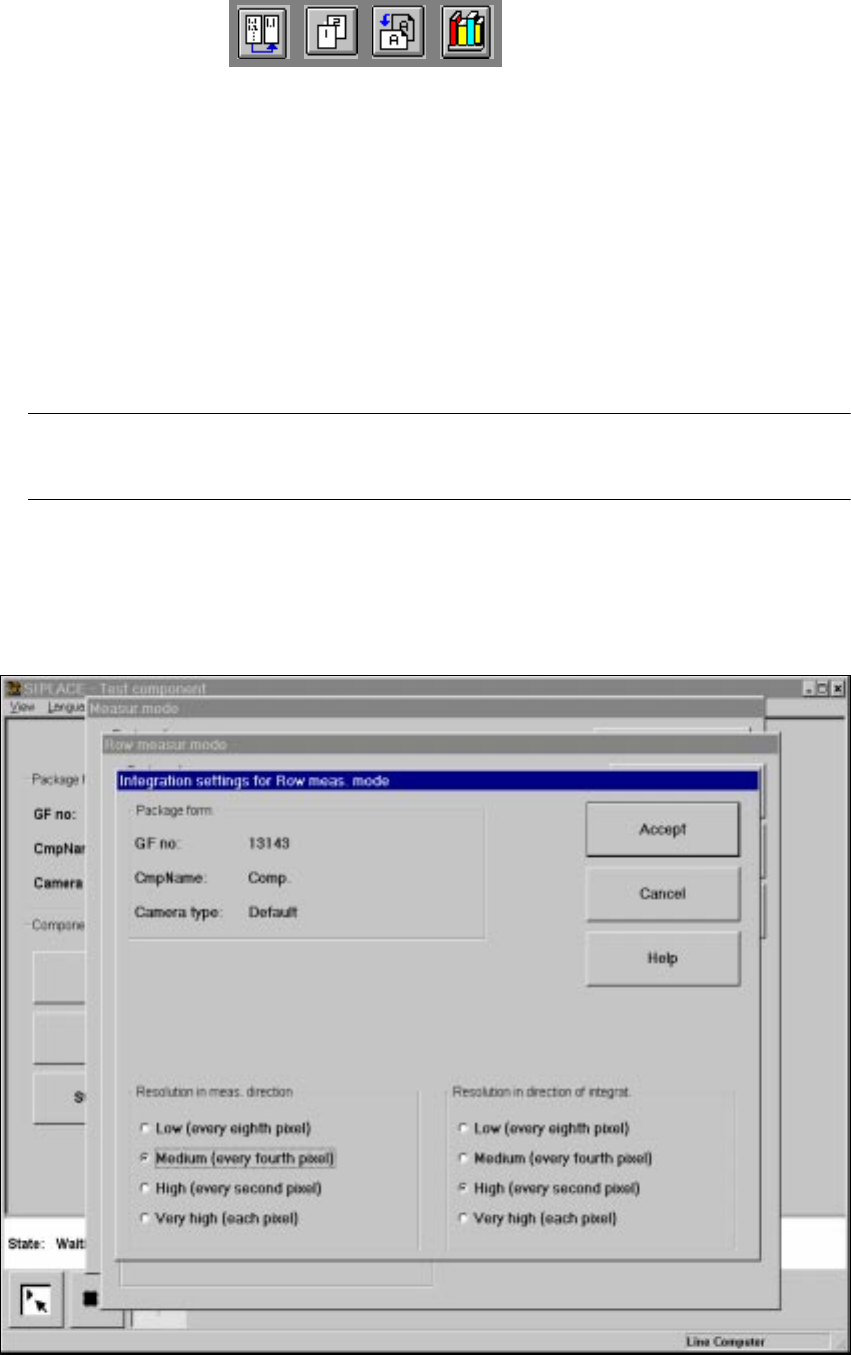
This menu is used to select the 6
– integration direction,
– the resolution in the measuring direction and
– the resolution in the integration direction.
Integration direction 6
In order to determine the angle, select the integration direction towards either the X or Y axis of
the component. We recommend that you select the longer edge. 6
Resolution in the measuring direction 6
Select this resolution in order to optimize the measuring times at the revolver head. 6
Resolution in the integration direction 6
Select this resolution in order to optimize the measuring times at the revolver head. 6
Resolution
in the measuring direction
Resolution
in the integration direction
Small components very high very high
Large components with another
measuring step to follow high medium
6 Vision functions User Manual HS-50
6.6 Test Component Software Version SR.501.xx 12/99 Issue US
294
t IIt
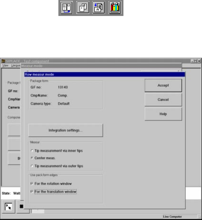
6.6.4.17 ’Row’ measuring mode
Click on the ‘Setting’ field in the Row measuring mode menu to call up the following menu: 6
6
Fig. 6.6 - 37 Measuring mode option, Row measuring mode menu
This menu is used to 6
– specify the lead measuring method.
– use the package form edges for the rotation windows and/or translation windows.
Measurement 6
If the inner lead tips are mapped better than the outer tips, for example, if a shiny lead is bent up-
wards slightly, you can select one of the following options: 6
– measuring the tips via the inner tips of the leads, for bases, for example
– center of the lead, center measurement, for PLCC, SOJ, for example
– measuring the tips via the outer tips of the leads, for QFP, SOT, SO, for example
User Manual HS-50 6 Vision functions
Software Version SR.501.xx 12/99 Issue US 6.6 Test Component
295
t IIt
Use package form edges 6
–
for rotation windows
The package form edges can be used to optimally position the rotation windows. However, to
do this, the package form edge must be visible and it must not contain a row of leads (eg white
plugs).
–
for translation windows
The package form edges can be used to optimally position the translation windows. However,
to do this, the package form edge must be visible and it must not contain a row of leads.
PLEASE NOTE:
Do not use measurement mode Row together with measurement mode Size. 6
Integration settings 6
Once you have clicked on the ‘Integration settings’ field, the Row measuring mode integration
settings menu will appear on screen. 6
6
Fig. 6.6 - 38 Measuring mode option, Row measuring mode integration settings menu