00191369-02.pdf - 第297页
User Manual HS-50 6 Vision functions Software Version S R.501.xx 12/99 Issue US 6.6 Test Comp onent 297 t I I t Measurement 6 If the inner lead ti ps are mappe d better tha n the oute r tips, for exam ple, if a s hiny l …
6 Vision functions User Manual HS-50
6.6 Test Component Software Version SR.501.xx 12/99 Issue US
296
t IIt
Measuring times can be reduced by lowering the resolution in the measuring or integration direc-
tion. However, you must ensure that the structure to be analyzed has a sufficient number of pixels.
Otherwise, the measuring quality will be compromised. We recommend to choose a very high or
high resolution. 6
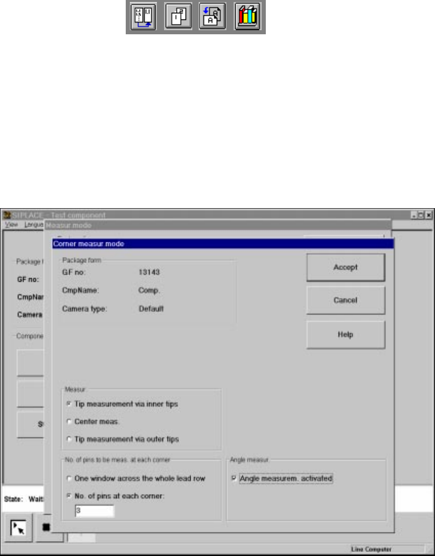
6.6.4.18 ‘Corner’ measuring mode
Click on the ‘Setting’ field in the ‘Corner’ measuring mode to call up the Corner measuring mode
menu. 6
6
Fig. 6.6 - 39 Measuring mode option, Corner measuring mode menu
This menu is used to 6
– specify the lead measuring method.
– select the number of leads to be measured at each corner.
– switch the angle measurement on or off.
User Manual HS-50 6 Vision functions
Software Version SR.501.xx 12/99 Issue US 6.6 Test Component
297
t IIt
Measurement 6
If the inner lead tips are mapped better than the outer tips, for example, if a shiny lead is bent up-
wards slightly, you can select one of the following options: 6
– measuring the tips via the inner tips of the leads, for bases, for example
– center of the lead, center measurement, for PLCC, SOI, for example
– measuring the tips via the outer tips of the leads, for QFP, SOT, SO, for example
Number of leads to be measured at each corner 6
If the lead does no longer stand out well from the background, in the case of white plugs, for ex-
ample, use this option to specify the number of leads to be measured. However, to do this, the
component must be fully described in the line computer (FDC). 6
NOTE 6
This value should only be modified for special components and plugs. Deactivate lead measure-
ment for white plugs.
Angle measurement 6
For single-row components, the angle of rotation is not calculated correctly. Consequently it is bet-
ter to access calculation of the angle of rotation in Row measuring mode. Switch off the angle
measurement in this option. 6
6 Vision functions User Manual HS-50
6.6 Test Component Software Version SR.501.xx 12/99 Issue US
298
t IIt
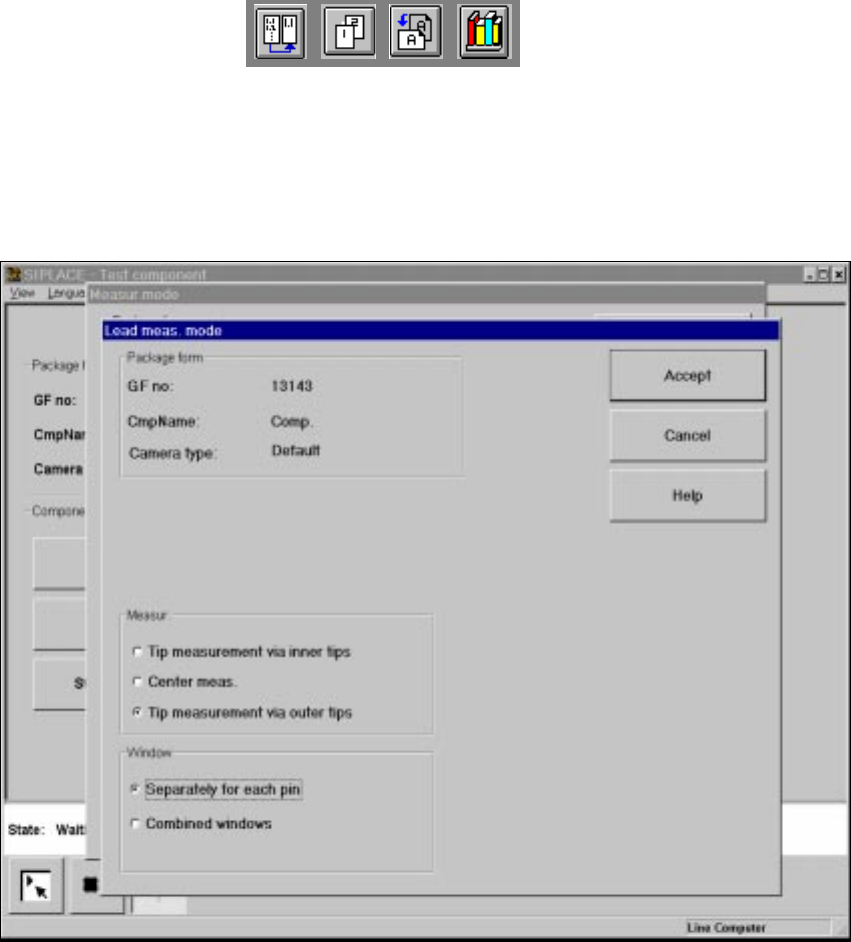
6.6.4.19 ‘Lead’ measuring mode
Click on the ‘Setting’ field in the ‘Lead’ measuring mode to call up the Lead measuring mode
menu. 6
6
Fig. 6.6 - 40 Measuring mode option, Lead measuring mode menu
This menu is used to 6
– specify the lead measuring method.
– to select the windows separately for each lead or a combined window for every lead to be mea-
sured.
Measurement 6
If the inner lead tips are mapped better than the outer tips, for example if a shiny lead is bent up-
wards slightly, you can select one of the following options: 6
– measuring the tips via the inner tips of the leads, for bases, for example
– center of the lead, center measurement, for PLCC, SOJ, for example
– measuring the tips via the outer tips of the leads, for QFP, SOT, SO, for example