00191369-02.pdf - 第305页
User Manual HS-50 6 Vision functions Software Vers ion SR.501.xx 12/99 Issue US 6.7 G uidelines for Describing Package Form s 305 t I I t 6 Fig. 6.7 - 3 Flow chart ’Programming and testing a package f orm (GF), part - l …

6 Vision functions User Manual HS-50
6.7 Guidelines for Describing Package Forms Software Version SR.501.xx 12/99 Issue US
304
t IIt
6.7.2 Flow Charts for Programming and Testing a Package Form (GF)
Components are optically centered in SIPLACE automatic placement systems. It is also neces-
sary to create the package form description for the component on the SIPLACE line computer first.
We recommend that you always take the package form definitions and dimensions from the data
sheet. 6
The package form settings can be modified at the station. There are different measuring methods.
This means that the lighting settings will also vary. Almost all components can be optically cen-
tered by combining all the setting options in the optimum manner. 6
You should note, however, that a great many package forms have already been defined as stan-
dard. This means that the manipulation of package forms at the station should be the exception,
rather than the rule. 6
We can also provide the package form definitions of special components and hard to center com-
ponents as an extra service. Contact us for further details of this application. 6
User Manual HS-50 6 Vision functions
Software Version SR.501.xx 12/99 Issue US 6.7 Guidelines for Describing Package Forms
305
t IIt
6
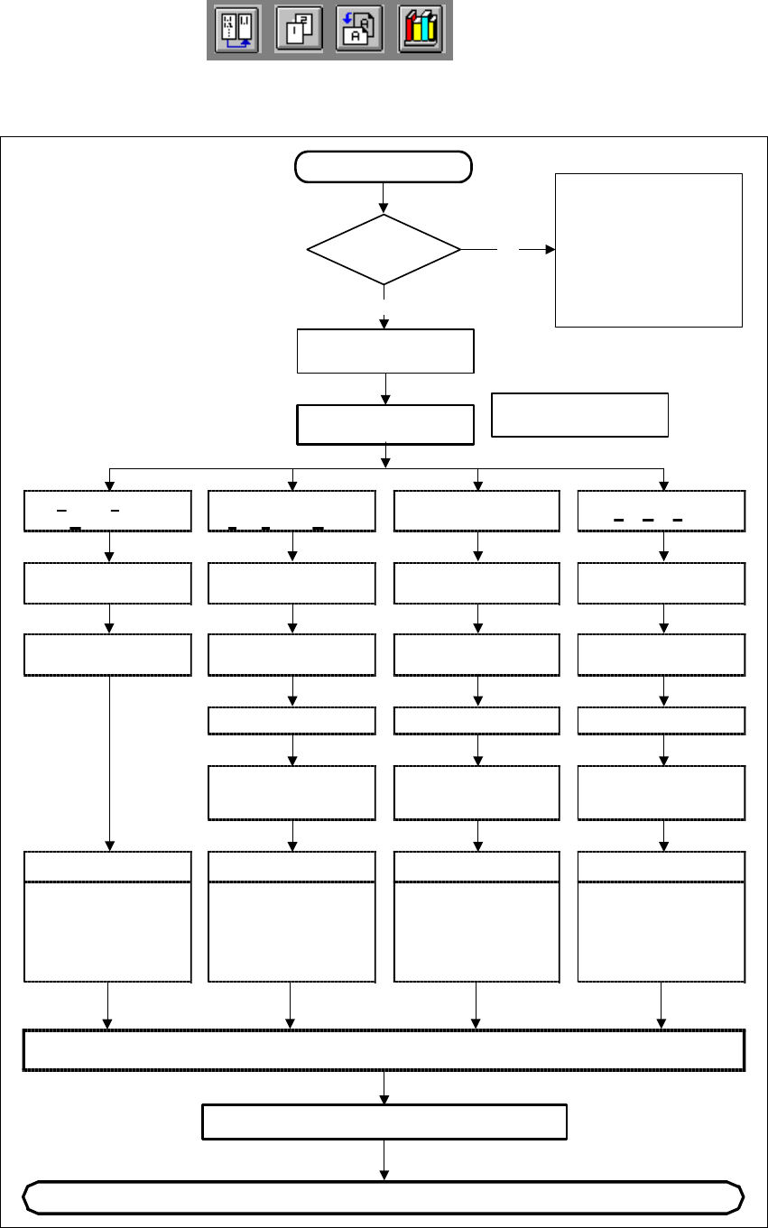
Fig. 6.7 - 3 Flow chart ’Programming and testing a package form (GF), part - line computer
Irregular
FDC
Regular
F
ully defined Comp.
P
artially defined
C
omponent
Ball GridArray
Body dimensions
Body dimensions Body dimensions
SAVE
Continue programming at the station
New component
GF file
present?
No
Yes
Program additional file information
Please note that when
standard package form
are used by TEST
COMPONENT,
the component detection
may be changed (copy the
GF file [ _.SST file ] again,
if necessary).
Program GF file with
No. > 1499
Select package type
Program GF file with
No. > 1499
Enter
user comment
Enter
user comment
Enter
user comment
Enter
user comment
GF nominal dimensions
and tolerances
GF nominal dimensions
and tolerances
GF nominal dimensions
and tolerances
GF nominal dimensions
and tolerances
Program
group of leads,
lead model data
Program
group of leads,
lead model data
Program
ball pitch,
lead model data
Editing data
Nozzle type (camera)
sensor system type,
vacuum checks/
editing parameters/
reduction in acceleration
Editing data
Nozzle type (camera)
sensor system type,
vacuum checks/
editing parameters/
reduction in acceleration
Editing data
Nozzle type (camera)
sensor system type,
vacuum checks/
editing parameters/
reduction in acceleration
Editing data
Nozzle type (camera)
sensor system type,
vacuum checks/
editing parameters/
reduction in acceleration
6 Vision functions User Manual HS-50
6.7 Guidelines for Describing Package Forms Software Version SR.501.xx 12/99 Issue US
306
t IIt
6
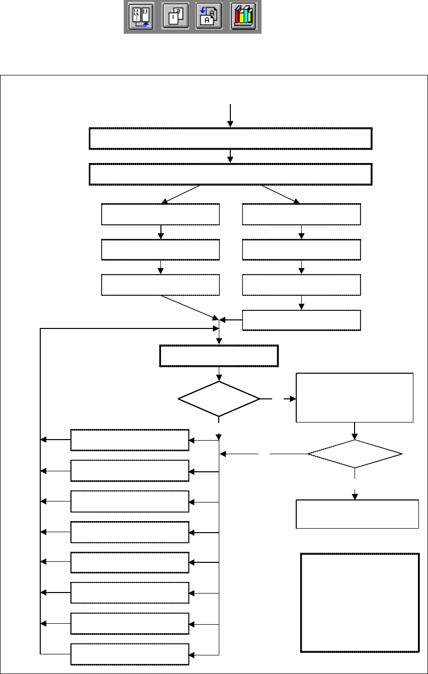
Fig. 6.7 - 4 Flow chart: ’Programming and testing a package form (GF)’, part 2 - station computer
Display component
Always identical?
No
No
Yes
Error message
occurred?
Yes
Modify package form as required in "Vision system“ and "Test component“
Send program and set-up with this package form to the station and set up
Revolver head
Pick-up GF (component)
Pick&Place placement head
Pick up GF (component)
Measure component
Check GF (component), press
Return for next meas. step
Display component
Check GF (component), press
Return for next meas. step
Measure GF (component)
Repeat meas. process several
times (move component onto
nozzle to simulate picking up
different components)
and check results
Assemble component
several times
Important note:
The manipulation of
components at the station
must remain the exception,
rather than the rule.
In general, only a few
components have to be
changed.
1. Handling error: pick-up angle,
nozzle type, CO on nozzle etc.
2. Display component
3. Modify lighting
4. Modify measuring modes
and measuring parameters
5. Modify component dimension
6. Modify pin/ball contrast
7. Modify pin/bal
dimensions
8. Program contrast
(program table)