00191369-02.pdf - 第309页
User Manual HS-50 6 Vision functions Software Vers ion SR.501.xx 12/99 Issue US 6.7 G uidelines for Describing Package Form s 309 t I I t 6.7.4 T est Package Form - Vi sual Represent ation / Programming Measurement T ype…

6 Vision functions User Manual HS-50
6.7 Guidelines for Describing Package Forms Software Version SR.501.xx 12/99 Issue US
308
t IIt
If the component cannot be centered correctly, additional measuring methods may be omitted.
You should, however, carry out all the rough centering steps since these reduce the size of the
measuring window. 6
– In the ’Test component’ menu, the components are optically centered in the individual measur-
ing steps, via the ’Check component’ function, but the results are not output.
– In the ’Test component’ menu, the components are optically centered in the individual measur-
ing steps, via the ’Measure component’ function, but the results are not output.
– If the components are larger than 32 mm x 32 mm, a multiple measurement will be carried out
automatically in the vision system.
User Manual HS-50 6 Vision functions
Software Version SR.501.xx 12/99 Issue US 6.7 Guidelines for Describing Package Forms
309
t IIt
6.7.4 Test Package Form - Visual Representation /
Programming Measurement Types
In the ’Test component’ menu, a component is picked up and then moved to the camera and
mapped in its 0° position. The component is displayed with respect to its placement angle at the
revolver head. 6
6
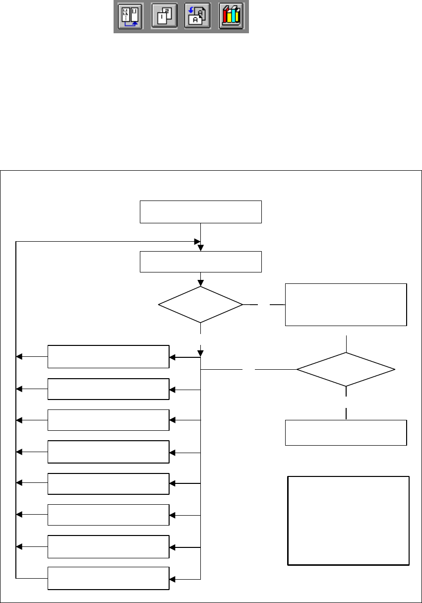
Fig. 6.7 - 5 Order in which package forms are programmed at the station
6
No
No
Yes
Error
1. Handling error: pick-up angle,
nozzle type, CO on nozzle etc.
2. Display component
3. Modify lighting
4. Modify measuring modes
and measuring parameters
5. Modify component dimension
6. Modify pin/ball contrast
7. Modify pin/ball
dimension
8. Program contrast
(program table)
Important note:
The manipulation of
components at the station must
remain the exception, rather
than the rule.
In general, only a few
components have to
be changed.
Assemble component
several times
Repeat measurement
and check the results
Measure component
Check component, press
Return for next meas. step
Are the results
constant?
Yes
6 Vision functions User Manual HS-50
6.7 Guidelines for Describing Package Forms Software Version SR.501.xx 12/99 Issue US
310
t IIt
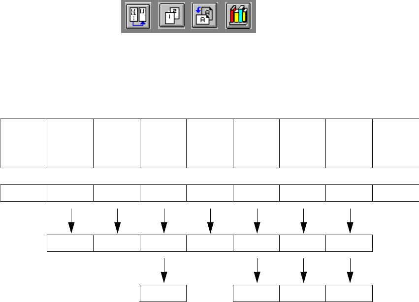
6.7.5 Parameters for the Measuring Methods
Possible sequences of measuring methods
It is also possible to program other sequences, such as corner followed by lead or lead only. Such
combinations are very unusual, however. If the component is defined in the package form editor,
then the measuring methods will be pre-assigned. However, in some cases it may be necessary
to modify the measuring methods at the station so that the component can also be optically cen-
tered. 6
The results from the last measurement are always saved. The previous measurement is used as
a rough centering step for the next measurement and thus helps to reduce the measuring window.6
The more measuring methods are used, the longer the entire measuring procedure will be. A large
number of measuring methods for a component can delay the head cycle. This applies to the re-
volver head in SIPLACE automatic placement machines, in particular. 6
PDC/
FDC FDC FDC FDC FDC FDC
Flip-
chips
HS50/
S20/F
Ball,
Grid array
Bare
dies
Size Size Size Size Row Row Size Size Size
Lead Corner Corner Corner Corner Grid Grid
Lead Lead Ball Ball