00191369-02.pdf - 第314页
6 Vision functions User M anual HS-50 6.7 Guidelines for Desc ribing Package Forms Software Version SR .501.xx 12 /99 Issue U S 314 t I I t As a rule y ou wil l not need to cha nge the illu mination par ameters for the s…
User Manual HS-50 6 Vision functions
Software Version SR.501.xx 12/99 Issue US 6.7 Guidelines for Describing Package Forms
313
t IIt
6.7.6.2 Pseudo color representation
The pseudo color representation provides a powerful and objective assessment of the illumina-
tion, by representing a brightness value in a color. 6
6
A contrast of at least 4 color scales between the lead and body is required for a measurement. In
the ‘Illumination’ menu of the package form manipulator, components are displayed in the pseudo
color representation on the station computer monitor. 6
6.7.6.3 Settings for Illuminating Standard Components
The standard range of components includes chips (0402 to 2220), tantalum capacitors, Melf com-
ponents, PLCCs, QFPs, SOs, SOJs, TSOPs, ICs, power components, flip-chips, µBGAs and
BGAs. 6
For the components which are listed below the GF interpreter in the station computer uses the
default illumination parameters listed in Fig. 6.7 - 7
: 6
– Chips (0402 to 2220)
– Tantalum capacitors (component bodies, non-reflective)
–Melf
– PLCC, QFP, SO, SOJ, TSOP, ICs, power ICs
– Flip-chips, µBGAs, BGAs (not ceramic BGAs)
Color scale Brightness
white light
yellow
orange
red
brown
green
light blue
blue
violet
black dark
Tab. 6.7.2
6 Vision functions User Manual HS-50
6.7 Guidelines for Describing Package Forms Software Version SR.501.xx 12/99 Issue US
314
t IIt
As a rule you will not need to change the illumination parameters for the standard components.
For all other components you will need to determine the illumination values and test them (see
Section 6.7.6.4
on page 314). 6
6
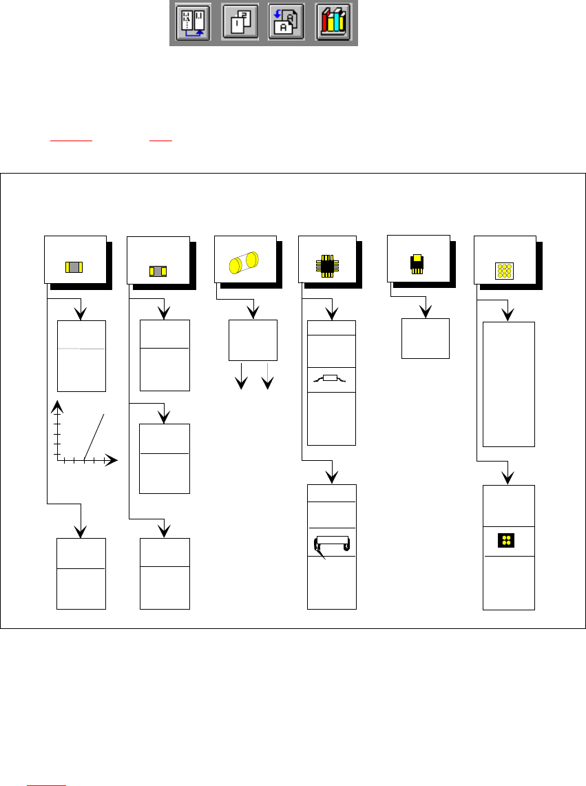
Fig. 6.7 - 7 Illumination parameters for standard components at the 12x revolver head camera
6
6
6.7.6.4 Settings for Illuminating Other Components
Fig. 6.7 - 8 presents a list of the illumination settings for other components. 6
flat: 255
middle: 90
steep: 60
Diagram for adjusting the illumination of standard components
Chip
IC
Power ICMelf
BGA, µBGA
flip-chip
Tantalum
capacitor
BGA,
µBGA,
flip-chip
0805 and
larger
0402,
0603
Light
General
flat: 120
middle: 40
steep: 170
Reflective
body
flat: 120
middle: 100
steep: 120
flat: 70
middle: 60
steep: 150
Gullwing
SO, SOT,
TSOP
QFP,
flat: 170
middle: 50
steep: 120
flat: 0
middle: 10
steep: 170
flat: 255
middle: 120
steep: 10
flat: 170
middle: 60
steep: 120
J-Lead
PLCC
flat: 80
middle: 40
steep: 120
Ceramic
BGA
flat: 0
middle: 50
steep: 255
flat: 255
middle: 20
steep: 0
Illumination
level
Brightness
150
255
Contrast
graduation
User Manual HS-50 6 Vision functions
Software Version SR.501.xx 12/99 Issue US 6.7 Guidelines for Describing Package Forms
315
t IIt
6
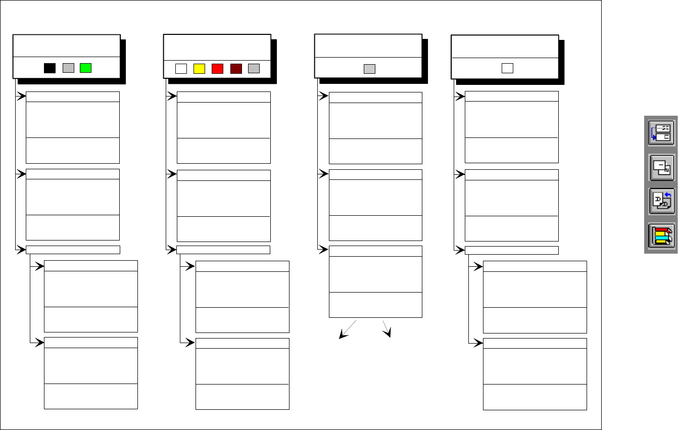
Fig. 6.7 - 8 Illumination parameters for other components at the 12x revolver head camera
Adjusting the illumination of other components
Light and dull body
( white, yellow, red, brown, grey,
metallic dull )
Ceramic body
Dark and dull body
( black, blue, green )
Reflective body
(independently of color and material)
Dull leads
flat: 70
middle: 60
steep: 150
Visual separation between leads
and body is not possible.
Illuminate body and leads equally.
Measure outline.
Shiny leads
Clear separation
between leads
and body.
Dull leads
flat: 150
middle: 120
steep: 0 - 20
Shiny leads
1. Illuminate body and leads equally.
Measure outline.
2. Trick: Use flat and middle levels to
bring leads image to saturation.
Measure.
Clear separation
between leads
and body.
for variant 2: flat: 150 - 255
middle: 60 - 150
steep: 0 - 20
flat: 200
middle: 80
steep: 0 - 20
flat: 120
middle: 80
steep: 0 - 20
Clear separation
between leads
and body.
Clear separation
between leads
and body.
J-Lead ( PLCC ), convex-type leads
Gullwing leads ( SO, QFP )
Dull leads
Shiny leads
flat: 120
middle: 50
steep: 170
flat: 170
middle: 50
steep: 120
Clear separation
between leads
and body.
Clear separation
between leads
and body.
J-Lead ( PLCC ), convex-type leads
Gullwing leads ( SO, QFP)
flat: 170
middle: 50
steep: 120
flat: 80
middle: 40
steep: 120
Clear separation
between leads
and body.
Clear separation
between leads
and body.
Other lead shapes
Dull leads
flat: 170
middle: 50
steep: 120
Visual separation between leads
and body is not generally possible.
Shiny leads
flat: 0
middle: 0 - 10
steep: 100 - 255
Clear separation
between leads
and body.
flat: 0
middle: 0 - 10
steep: 150 - 255
Leads:
Outline:
Measuring method:
Visual separation between leads
and body is not possible.
Illuminate body and leads equally.
Measure outline.
flat: 170
middle: 50
steep: 120
Visual separation between leads
and body is not possible. Measure
outline or lead tips. Leads are
outside the body.
flat: 80
middle: 40
steep: 120
J-Lead ( PLCC ), convex-type leads
Gullwing leads ( SO, QFP )
Other lead shapes
Convex-type leads
flat: 70
middle: 60
steep: 150
Other lead shapes
flat: 0
middle: 0 - 20
steep: 200 - 255
Visual separation between leads
and body is not generally possible.
Illuminate body and leads equally.
Measure outline.
Illumination level Brightness