00191369-02.pdf - 第324页
7 What should you do ... User Manual HS -50 7.1 Switching on the SIPLACE line Software V ersion SR.501.xx 12 /99 Issue US 324 t I I t Å Pr ess one of the start k eys (w hite) whe n prompted with " Press star t key&q…
User Manual HS-50 7 What should you do ...
Software Version SR.501.xx 12/99 Issue US 7.1 Switching on the SIPLACE line
323
t IIt
7.1.3 Switching on the station / starting the user interface of the station computer
program
ATTENTION
Switch on the station only after the desktop is displayed on the line computer monitor. Otherwise,
communication problems may occur. 7
Å Switch on the station on the main switch and check to see if the manometer displays the re-
quired operating pressure after you have switched the station on.
The station computer software is uploaded. When the line computer is connected and commu-
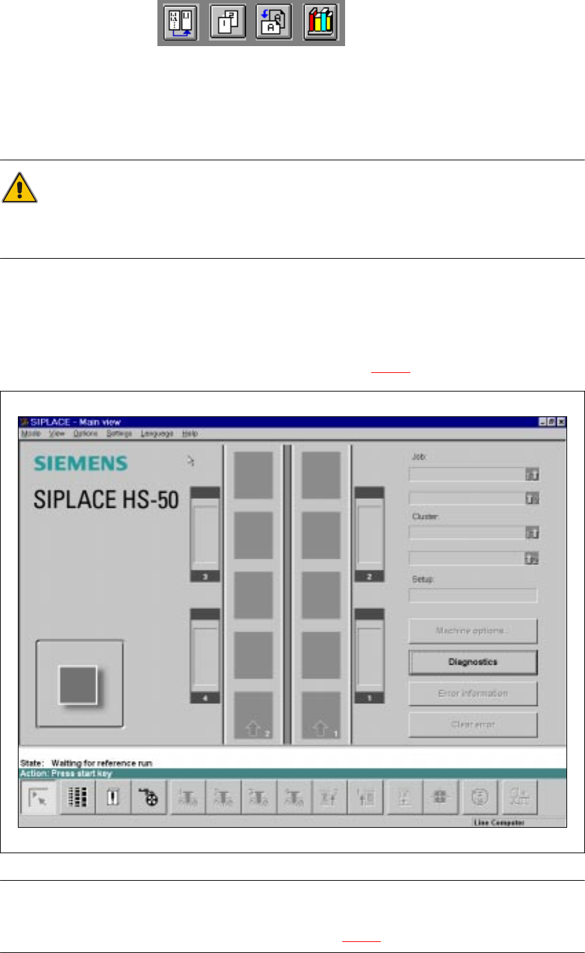
nication is error-free, the Main view of the station computer user interface appears for the "Op-
erator" user class after approximately 2 minutes (see Fig. 7.1 - 1
).
7
Fig. 7.1 - 1 Main view after loading the station computer software
NOTE
The current state of the station is displayed in the status field in the "State" line, and the action you
are to execute is displayed in the "Action:" line (see Fig. 7.1 - 1). 7
7 What should you do ... User Manual HS-50
7.1 Switching on the SIPLACE line Software Version SR.501.xx 12/99 Issue US
324
t IIt
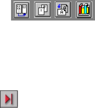
Å Press one of the start keys (white) when prompted with "Press start key".
(The start keys are located on the input side, output side and on the control panels on the left
and right sides of the station.)
A reference sequence is executed on all axes. The station is ready for operation after the ref-
erence sequence has completed.
The symbol is displayed in the work area of the user interface.
7
7
7
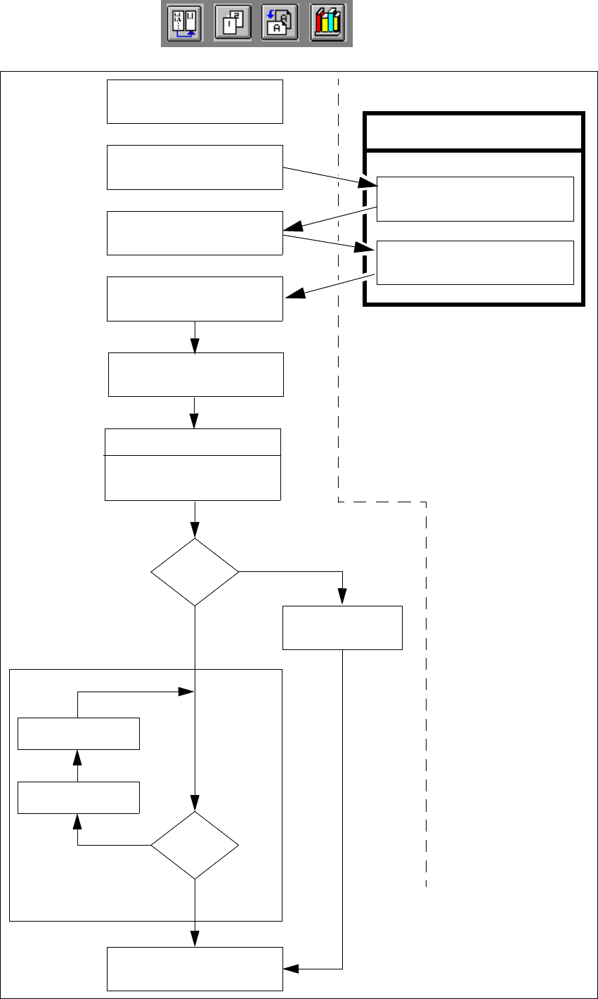
7.1.4 "Switching on the SIPLACE line" flow chart
The following flow chart shows the actions executed be the line computer, station and operator
while the SIPLACE line is being switched on and started up. 7
7
User Manual HS-50 7 What should you do ...
Software Version SR.501.xx 12/99 Issue US 7.1 Switching on the SIPLACE line
325
t IIt
7
Fig. 7.1 - 2 "Switching on the SIPLACE line“ flow chart
Test set-up
Reset tracks
No
Line computer tasks
Load cluster data
Fiducials
OK?
Make settings on the machine
Set-up generator appears
Check the set-up
(insert feeder modules)
Switch on
Nozzle check
Change nozzle
configuration, if necessary
Wait for PCB
Introduce PCB
Track
errors
Ye s
Abort
placement
Ye s
PCB onto output conveyor
No
Station computer
Bold :
Italic :
To be carried out
by the operator
Carried out or
signaled by the
station
Confirm the
set-up generator