00191369-02.pdf - 第33页
User Manual HS-50 1 Introduction Software Version S R.501.xx 12/99 Issue US 1.10 Setting up the placement system 33 t I I t 3 x 16 A f or 3 x 380 V AC 1 3 x 16 A f or 3 x 400 V AC 1 3 x 16 A f or 3 x 415 V AC 1 1.10.6 Se…

1 Introduction User Manual HS-50
1.10 Setting up the placement system Software Version SR.501.xx 12/99 Issue US
32
t IIt
1.10.2 Transport configuration and transportation
The following components are not installed when the placement system is delivered from the fac-
tory: 1
– keyboards
– monitors
– fault indicator lamps and
– component tables
Å Install the dismantled components for commissioning.
Å Use a fork-lift truck to transport the placement system:
– minimum fork length 2000 mm if the mounting kit is dismantled.
– minimum fork length 2500 mm if the mounting kit is still fitted.
Å Attach the fork-lift truck only at the indicated points.
1.10.3 Quality of the foundation
Å Ensure that
– you set up the placement system on a firm and non-vibrating foundation.
– the load bearing capacity per unit area of the foundation is greater than 1000 kg/m².
1.10.4 Compressed air supply
– The pressure of the compressed air supply must be 6.5 bar min.
– The compressed air must conform to the above specification.
This can be achieved with 1
– oil-free compressors, e.g. Atlas, Copco type ZR4
– compressed air washer/driers
– micro-filters, series X, e.g. from Zander
1.10.5 Power supply
– The power socket must be fused with the following fuse ratings:
3x32A for 3x204VAC 1
3x32A for 3x230VAC 1
User Manual HS-50 1 Introduction
Software Version SR.501.xx 12/99 Issue US 1.10 Setting up the placement system
33
t IIt
3 x 16 A for 3 x 380 VAC 1
3 x 16 A for 3 x 400 VAC 1
3 x 16 A for 3 x 415 VAC 1
1.10.6 Setting up the placement system
Å Raise the placement system using the fork-lift truck and adjust the feet until there is a gap of
830 mm (952.5 mm SMEMA height) between the top edge of the PCB conveyors and the bot-
tom edge of the feet.
Å Leave a gap of 1 to 3 mm between the PCB conveyors of the placement system.
Å Use a cord pulled tight to ensure that all the placement systems are exactly in line with one
another.
Å Adjust each placement system using a spirit level with an accuracy of 0.02 mm/m.
Å Lock the feet in position.
Å Check the placement system again using the spirit level and correct the settings, if necessary.
CAUTION
Make sure that you remove all the shipping braces from the placement system. 1
Å Fit any components that were dismantled for dispatch.
Å Connect all the electrical and pneumatic lines.
RISK OF DEATH
The electrical connection work MUST be carried out only by appropriately trained and certi-
fied personnel. 1
1 Introduction User Manual HS-50
1.11 Overview of the modules - controls Software Version SR.501.xx 12/99 Issue US
34
t IIt
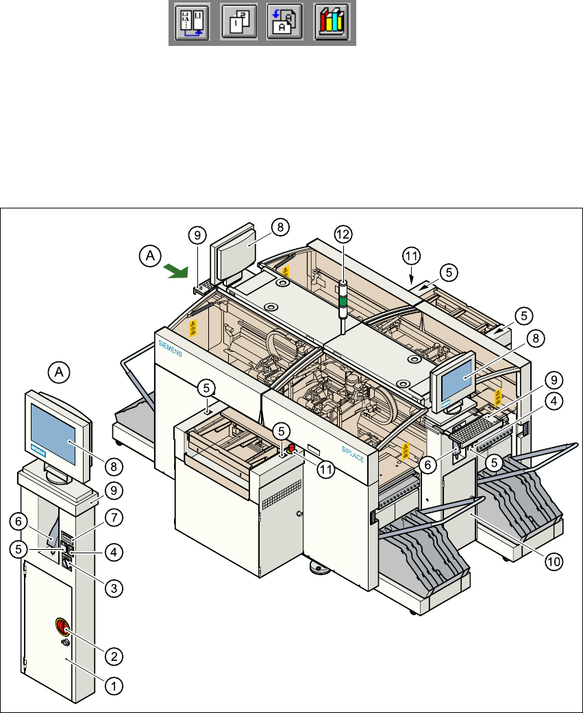
1.11 Overview of the modules - controls
1.11.1 Controls
1
Fig. 1.11 - 1 Overview of the modules - controls
1
(1) Operating panel, left-hand side (2) Main switch
(3) Key switch (4) Stop button (black)
(5) Start button (white) (6) Component barcode scanner
(7) Component counter (8) LCD screen
(9) Keyboard with trackball (10) Operating panel, right-hand side
(11) Emergency stop mushroom-head push-button (12) Indicator lamps