00191369-02.pdf - 第376页
10 Component handling User Manual HS-50 10.5 Used tape cutter Software V ersion SR.501.xx 12/99 Issue U S 376 t I I t The used tape guide c hannel s (see item 1 in Fig. 10.5 - 3 ) ar e locat ed upstream of the feeder mod…
User Manual HS-50 10 Component handling
Software Version SR.501.xx 12/99 Issue US 10.5 Used tape cutter
375
t IIt
10.5.2 Feeding the used tape to the cutter
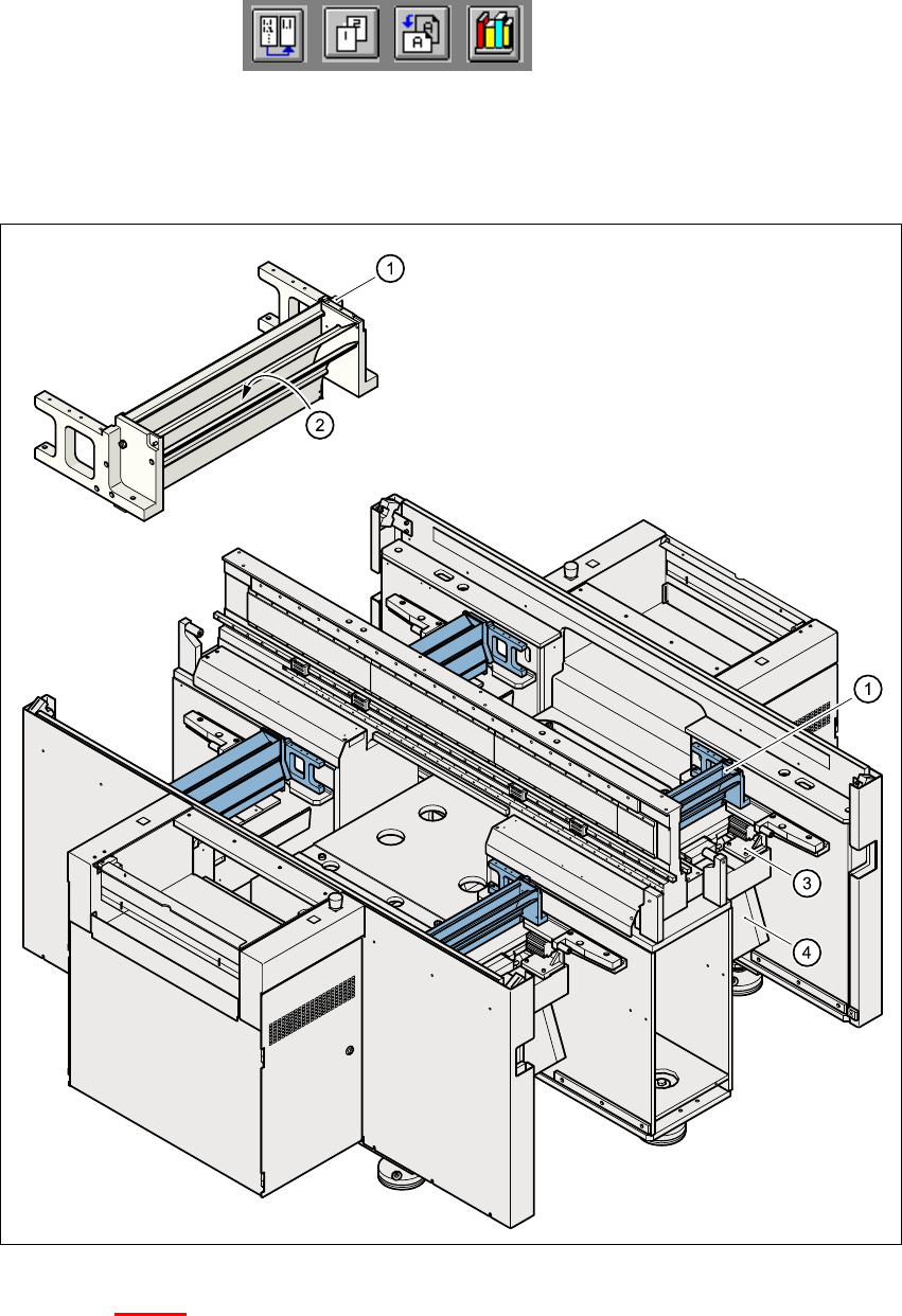
Fig. 10.5 - 3 Feeding the used tape to the cutter
Key to Fig. 10.5 - 3
(1) Used tape guide channel
(2) Channel for removal of the used tape
(3) Tape cutter
(4) Waste tape chute
10 Component handling User Manual HS-50
10.5 Used tape cutter Software Version SR.501.xx 12/99 Issue US
376
t IIt
The used tape guide channels (see item 1 in Fig. 10.5 - 3) are located upstream of the feeder mod-
ules. They are positioned directly above the used tape cutters (see item 3 in Fig. 10.5 - 3
). 10
The tape is automatically guided through the used tape guide channel into the used tape cutter
below. There, the tape is shredded by the pneumatically-actuated cutting blade. The waste tape
then passes via the waste tape chute (see item 4 in Fig. 10.5 - 3
) into the component table’s waste
container. 10
10
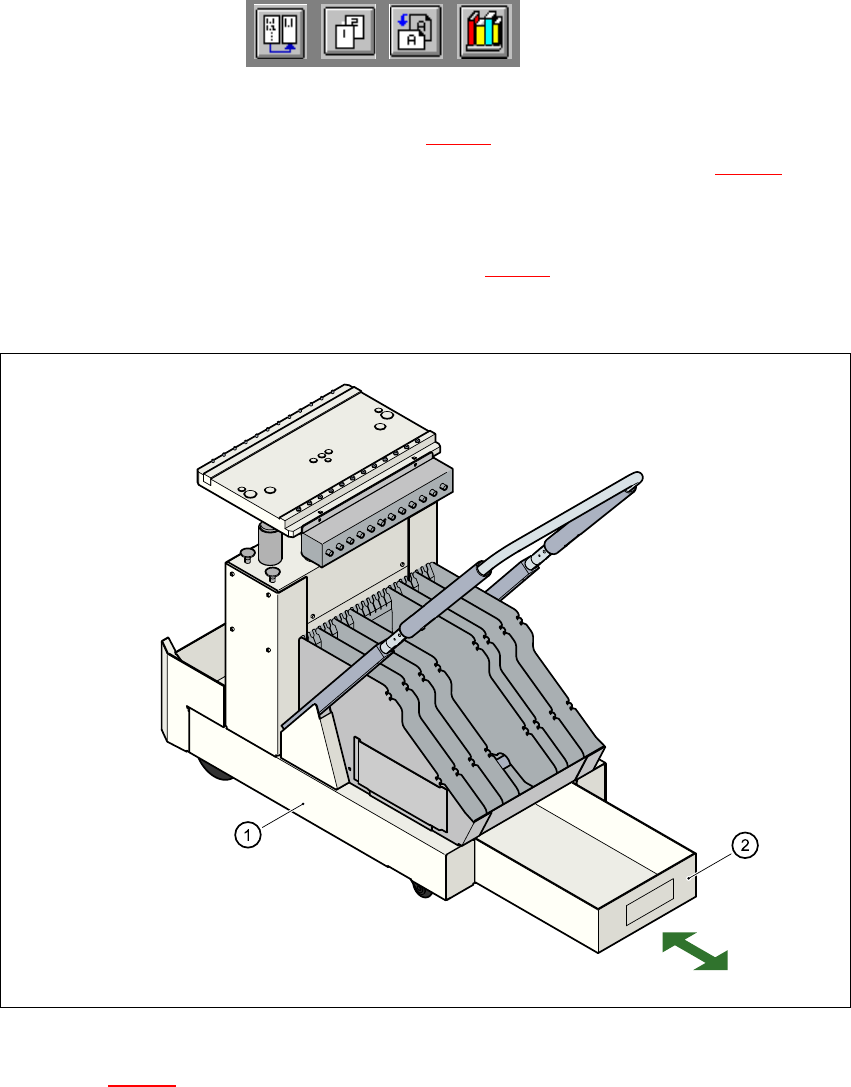
Fig. 10.5 - 4 Removable waste tape container in the component changeover table
Key to Fig. 10.5 - 4
(1) Component changeover table
(2) Removable waste tape container
10
User Manual HS-50 10 Component handling
Software Version SR.501.xx 12/99 Issue US 10.6 Component changeover tables
377
t IIt
10.6 Component changeover tables
10.6.1 Safety instructions for docking and undocking the component changeover
table
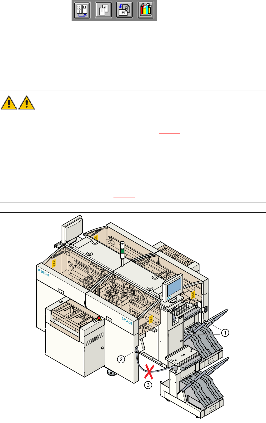
WARNING 10
Å Never reach into the gaps between the component changeover table and the placement sys-
tem frame while the machine is running (item 1 in Fig. 10.6 - 1
).
Å Always check that the component changeover table is docked on the placement system before
connecting or disconnecting the power cable for the component changeover table at the socket
on the placement system (item 2 in Fig. 10.6 - 1
).
Å NEVER connect the connecting cable for the component changeover table to the socket on the
placement system and then operate the component table outside the machine via the com-
pressed air control unit (item 3 in Fig. 10.6 - 1).
10
Fig. 10.6 - 1 Safety instructions for the component changeover table