00191369-02.pdf - 第393页
User Manual HS-50 11 S tation extensions / hardware Software Version S R.501.xx 12/99 Issue US 11.3 Dual conveyor 393 t I I t 1 1.3.6. 1 Automatic wid th adjust ment on the dual conveyor PLEASE NOTE 11 The conve yor set …

11 Station extensions / hardware User Manual HS-50
11.3 Dual conveyor Software Version SR.501.xx 12/99 Issue US
392
t IIt
11.3.2 General
As the name suggests, the dual conveyor has two transport tracks, which are electrically and me-
chanically independent of one another. In the Standard version, the right-hand side is the fixed
side. There is another version, however, in which the left-hand side is the fixed side. 11
11.3.3 Defining the transport tracks
The right transport track (viewed in the transport direction) is designated "Transport 1" and the left
as "Transport 2" (see Fig. 11.3 - 1
). 11
11.3.4 Asynchronous conveyor mode
11.3.4.1 Description
In asynchronous mode, only one PCB in a transport track is processed. At the same time, another
PCB in the second transport track is moved into the placement position. This saves the full con-
veying time of one PCB, thus considerably increasing performance, particularly for PCBs with a
short cycle time. 11
11.3.5 Function
Once the machine has received the job data (cluster, set-up), the PCBs on the feeding belts are
continuously transported to the available processing belt (provided that the belt is free) throughout
the placement operation. The placement sequence starts as soon as a PCB has moved onto the
relevant processing belt. The PCBs are processed one after another. 11
11
If the placement sequence is interrupted, the conveyor interface will be disabled and the PCBs
currently on the processing belts will be completed. 11
The conveyor interface is disabled or enabled simultaneously for both transport tracks. 11
11.3.6 Controlling the dual conveyor with the Single functions menu
Control of the dual conveyor and the Single functions menu are described in section 5 of these
operating instructions. 11

User Manual HS-50 11 Station extensions / hardware
Software Version SR.501.xx 12/99 Issue US 11.3 Dual conveyor
393
t IIt
11.3.6.1 Automatic width adjustment on the dual conveyor
PLEASE NOTE 11
The conveyor setpoint width relates to both conveyor belts. When the command is received, the
conveyor belts are set to the setpoint width one after another.
11.3.7 Technical data for the dual conveyor
11
11.3.8 Maintenance
The individual conveyor belts and the additional lifting table require the same maintenance as the
standard conveyor. Each conveyor belt must be maintained as described in the maintenance in-
structions. 11
Fixed conveyor edge Right (standard), left (optional)
PCB format
50 mm x 50 mm to 368 mm x 216 mm
2" x 2" to 14.5" x 8.5"
PCB thickness 0.3 mm to 4.5 mm
Maximum PCB curvature
On top: 4.5 mm - PCB thickness
On bottom: 0.3 mm + PCB thickness
Clearance underneath PCB
Standard: 25 mm
Option: Up to 40 mm
PCB conveyor height
830 ± 15 mm (standard)
950 ± 15 mm (option) SMEMA
Type of interface
Siemens (standard)
SMEMA (option)
Clear guide edge of component 3 mm
PCB changeover time 2.5 s
Components on each conveyor Same or different
PCB width on each conveyor Same or different
Ink spot recognition Possible
Automatic width adjustment Possible
Tab. 11.3 - 1
11 Station extensions / hardware User Manual HS-50
11.4 Feeder position recognition Software Version SR.501.xx 12/99 Issue US
394
t IIt
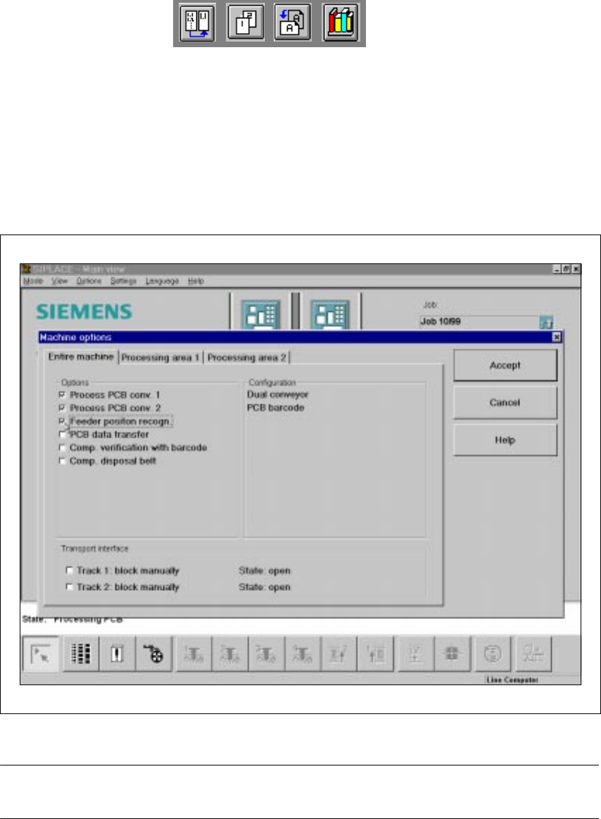
11.4 Feeder position recognition
If the feeder modules are equipped with positioning fiducials, the fiducials can be measured.
If the "Conveyor position detection" function has been selected on the line computer, the function
will also appear in the Machine options. It can then be activated or deactivated at each station.
11
Fig. 11.4 - 1 Feeder position recognition
PLEASE NOTE 11
The "Feeder position recognition" function is always deactivated when the station is switched on.
If a track has been entered in the cluster data, the PCB camera on the feeder module will ap-
proach the position of the centering fiducial. Any centering fiducial offset determined during the
measurement will then be assigned to this track and added to the pick-up position during the pick-
up operation. 11