00191369-02.pdf - 第41页
User Manual HS-50 1 Introduction Software Version S R.501.xx 12/99 Issue US 1.12 Overview of the modules - gantries 41 t I I t 1.12.3 T echnical dat a for the X- axis 1.12.4 Struct ure of the Y -axis 1 Fig. 1.12 - 3 S tr…
1 Introduction User Manual HS-50
1.12 Overview of the modules - gantries Software Version SR.501.xx 12/99 Issue US
40
t IIt
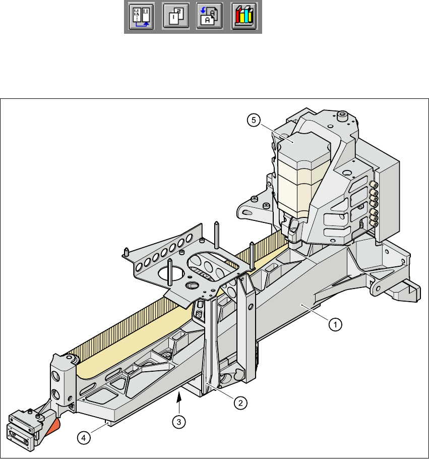
1.12.2 Structure of the X-axis
1
Fig. 1.12 - 2 Structure of the X-axis
The X-axis essentially consists of the following main modules: 1
– gantry arm (1)
– head mount (2)
– linear measuring system (3)
– X-axis guide system (4)
– X-axis three-phase AC servomotor (5)
The head mount holds the following components 1
– sub-gantry camera (camera for the PCB vision system)
– head board
– measuring head for the X-axis measuring system
– revolver placement head
User Manual HS-50 1 Introduction
Software Version SR.501.xx 12/99 Issue US 1.12 Overview of the modules - gantries
41
t IIt
1.12.3 Technical data for the X-axis
1.12.4 Structure of the Y-axis
1
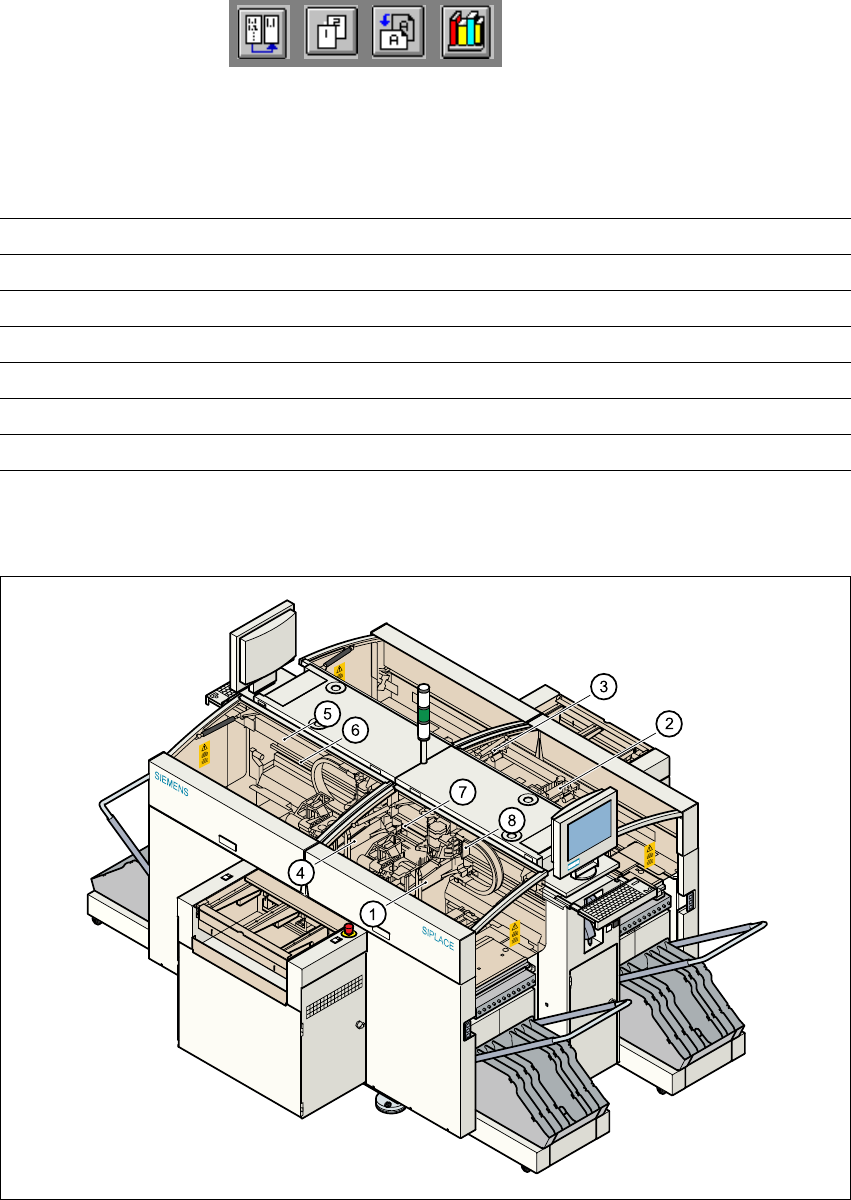
Fig. 1.12 - 3 Structure of the Y-axis
Drive Three-phase AC servomotor/toothed belt
Maximum speed 2.5 m/sec.
Traversing path 375 mm
Distance measuring system Metal linear scale
Measured length 400 mm
Scale length 420 mm
Resolution 1 µm
(1) Gantry 1 (2) Gantry 2
(3) Gantry 3 (4) Gantry 4
(5) Permanent magnet (6) Guide system
(7) Measuring system (8) Adapter plate

1 Introduction User Manual HS-50
1.12 Overview of the modules - gantries Software Version SR.501.xx 12/99 Issue US
42
t IIt
The Y-axis essentially consists of the following main modules: 1
– Y-axis linear drive with permanent magnet (1) and adapter plate (2)
– Y-axis guide system
– Y-axis measuring system
1
The Y-axis is driven by a linear motor. The secondary part of the drive is made up of permanent
magnets and is mounted on the machine frame. The primary part is bolted to the gantry (adapter
plate). An anti-crash circuit prevents the traversing paths of the gantries meeting. 1
1.12.5 Technical data for the Y-axis
Drive Direct, linear motor
Maximum speed 2.5 m/sec.
Traversing path of the gantries. calculated
from the center of the machine:
Gantry 1 - 688.5 mm
Gantry 2 - 768.5 mm
Gantry 3 - 688.5 mm
Gantry 4 - 768.5 mm
Distance measuring system Metal linear scale
Scale length 1530 mm
Resolution 1 µm