00191369-02.pdf - 第61页
User Manual HS-50 2 Operational Safety Software Version S R.501.xx 12/99 Issue US 2.1 Safety instructions 61 t I I t 2.1.8 Safety instructions for the PCB barcode reader (option) 2 Fig. 2.1 - 4 PCB barcode reader CAUTION…
2 Operational Safety User Manual HS-50
2.1 Safety instructions Software Version SR.501.xx 12/99 Issue US
60
t IIt
2.1.7 Safety instructions for changing the component table
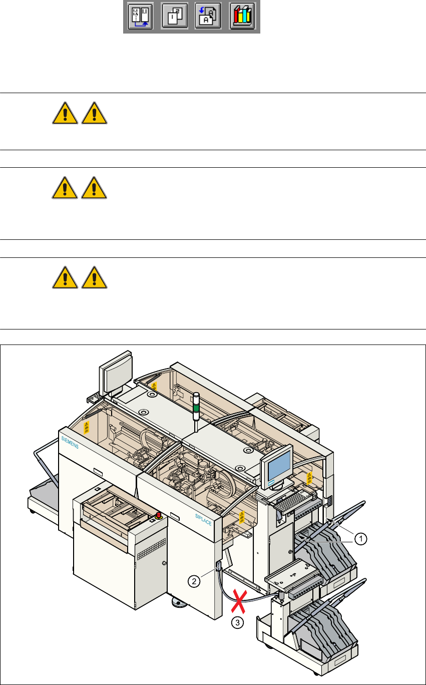
WARNING Never reach into the gaps between the component changeover table
and the placement system frame while the machine is running (item 1 in Fig. 2.1 - 3). 2
WARNING Always check that the component table is docked on the placement sys-
tem before connecting or disconnecting the power cable for the component changeover table at
the socket on the placement system (item 2 in Fig. 2.1 - 3). 2
WARNING NEVER connect the connecting cable for the component table to the
socket on the placement system and then operate the component table outside the machine via
the compressed air control unit (item 3 in Fig. 2.1 - 3). 2
2
Fig. 2.1 - 3 Safety instructions for the component table
User Manual HS-50 2 Operational Safety
Software Version SR.501.xx 12/99 Issue US 2.1 Safety instructions
61
t IIt
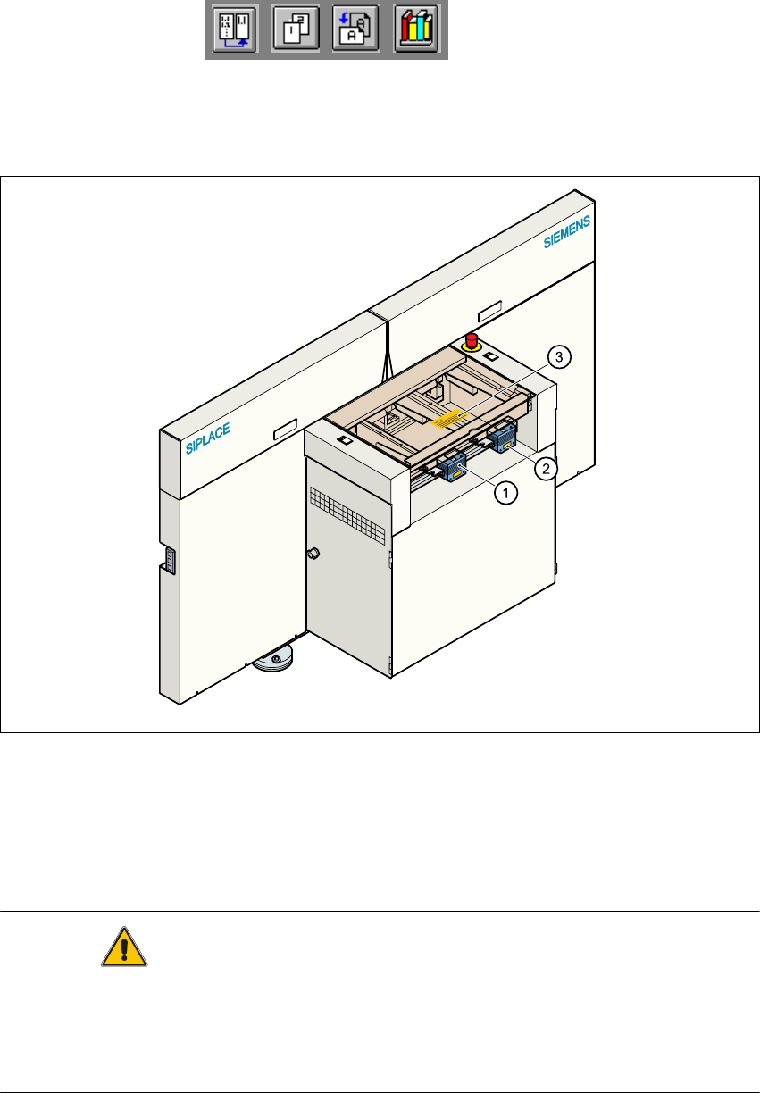
2.1.8 Safety instructions for the PCB barcode reader (option)
2
Fig. 2.1 - 4 PCB barcode reader
CAUTION The radiant power of the barcode reader’s scanning beam is less than 1 mW.
This means that the barcode reader conforms to laser class 2 and, according to DIN EN 60825-
1, requires no special safety equipment or protective measures. NEVER look into the laser beam.
There is also a safety circuit that switches off the laser diode if the polygon wheel stops or turns
too slowly. 2
(1) PCB barcode reader
(2) Label: LASER RADIATION...
(3) Label: CAUTION ...
2 Operational Safety User Manual HS-50
2.1 Safety instructions Software Version SR.501.xx 12/99 Issue US
62
t IIt
2
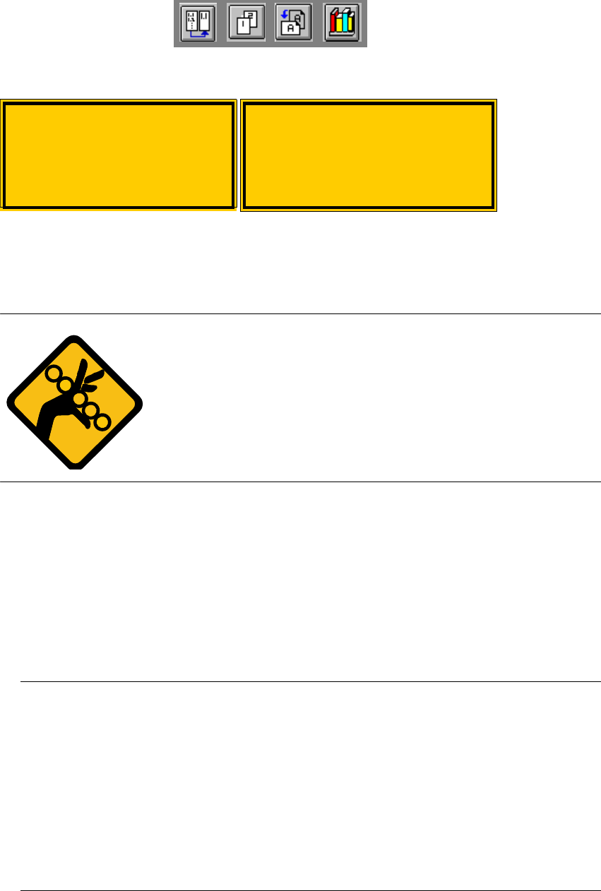
Fig. 2.1 - 5 Label: Laser radiation
6DIHW\LQVWUXFWLRQVIRUFKDQJLQJWKHKHL JKWRIFRPSRQHQWWDEOH V
WARNING 2
The component table must only be converted to modify the default
height by trained Service personnel.
Act with considerable care during the conversion process since
the system contains large weights or compression springs (potential
energy).
&RQYHUWLQJWKHFRPSRQHQWWDEOHWRVXLWDGLIIHUHQWOLQHKHLJKW
Å Use the placement system’s pneumatic controller to raise the table bed. Then insert a 120mm
spacer block between the table bed and cross-beam, and lower the bed onto the block.
Å Dismantle the internal paneling.
Å Swivel the handle down. The latching disk swivels down as well.
Å Set the screw to the desired dimension and lock in place with the locknut.
3/($6(127(
,I\RXFDQQRWORRVHQWKHDGMXVWLQJVFUHZIDUHQRXJKWKHFURVVEHDPPX VWEHUDLVHG
Å )L[WKHOLIWLQJGHYLFHWRWKHFURVVEHDP
Å &DUHIXOO\RSHQWKHFURVVEHDPFODPS
Å 5DLVHWKHFURVVEHDPXQWLOWKHHQGRIWKHWXEHSURMHFWVDSSUR[PPRXWRIWKHFODPS
Å 7LJKWHQWKHFURVVEHDPFODPS
Å 7KHQWXUQWKHDGMXVWLQJVFUHZWRWKHGHVLUHGGLPHQVLRQDQGORFNLQSODFHZLWKWKHORFNQXW
Laser radiation
Do not look into beam
Class 2 laser product
$WWHQWLRQ
/DVHUUDGLDWLRQLIWKHFRYHU
LVRSHQHGDQGWKHVDIHW\
LQWHUORFNLVE\SDVVHG
'RQRWORRNLQWREHDP