00191369-02.pdf - 第75页
User Manual HS-50 2 Operational Safety Software Version S R.501.xx 12/99 Issue US 2.2 Safety equipment 75 t I I t 2 Fig. 2.2 - 7 HS-50 safety loop PCC*) y axis x axis star ax is dp axi s z axis PCB conveyor PCB c lam pin…

2 Operational Safety User Manual HS-50
2.2 Safety equipment Software Version SR.501.xx 12/99 Issue US
74
t IIt
The two signalling contacts for the emergency stop mushroom-head push-button are connected
in parallel and form the "Emergency stop mushroom-head push-button signal" circuit. When an
emergency stop mushroom-head push-button is pressed, a 24 V signal is sent to the CAN bus
and signals that one of the emergency stop mushroom-head push-buttons has been pressed. 2
The four signalling contacts for the push-button flaps are connected in parallel. They form the
"Flaps signal" circuit. If one or more flaps is raised, a 24 V signal is applied to the CAN bus and
signals that one of the cover flaps is not closed. 2
The four signalling contacts for the component tables are connected in series and form the "Com-
ponent table signal" loop. If a component table is missing, a 0 V signal is sent to the CAN bus. If
all the tables are connected, the signal is approximately 16 V. 2
2.2.4.3 Functional description of the safety circuit
The following conditions must be fulfilled before the placement system can be started or oper-
ated:
– all four component changeover tables must be docked and connected.
– all covers - four over the gantries, one over the PCB input belt and one over the output belt -
must be closed.
– both emergency stop mushroom-head push-buttons must be released
– all four flaps over the push-buttons for raising and lowering the component changeover tables
must be closed.
– the minimum operating pressure must have been reached.
– the software enable must have been given, thus activating the safety circuit.
– the power supply must be sending 24 V to the Start buttons and the protective contactor com-
bination.
– If one of the Start buttons is now pressed, the protective contactor combination (PCC) will
switch and activate the following components:
– 200 V link voltage for the servo amplifier for the gantry axes
– 100 V link voltage for the star axes
– 230 V operating voltage for the lifting table motors
– the servo unit will receive a "Servo enable" signal for the servo amplifier
– 34 V operating voltage is switched to the component changeover tables
– 24 V operating voltage is switched to the used tape cutters.
The machine is now ready for service. 2
User Manual HS-50 2 Operational Safety
Software Version SR.501.xx 12/99 Issue US 2.2 Safety equipment
75
t IIt
2
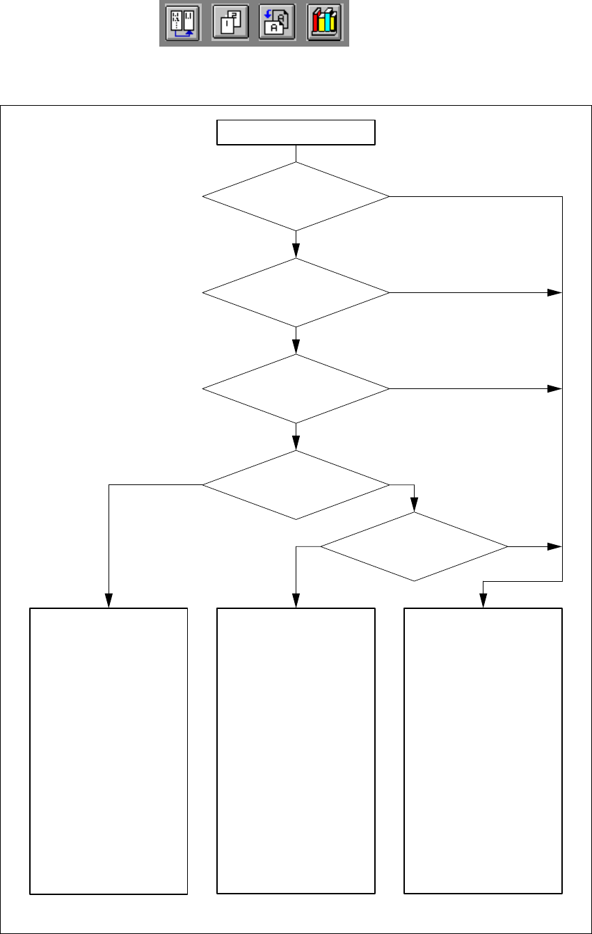
Fig. 2.2 - 7 HS-50 safety loop
PCC*)
y axis
x axis
star axis
dp axis
z axis
PCB conveyor
PCB clamping
Width adjustment
PCB stopper
Lifting table
Used tape cutter
Active
Yes
Voltage
200V
200V
100V
30V
30V
Active
Yes
Yes
Yes
Yes
Yes
Yes
PCC*)
y axis
x axis
star axis
dp axis
z axis
PCB conveyor
PCB clamping
Width adjustment
PCB stopper
Lifting table
Used tape cutter
Active
No
Voltage
0V
0V
6V
30V
30V
Active
Yes
No
Yes
No
No
No
PCC*)
y axis
x axis
star axis
dp axis
z axis
PCB conveyor
PCB clamping
Width adjustment
PCB stopper
Lifting table
Used tape cutter
Active
No
Voltage
0V
0V
6V
30V
30V
Active
No
No
No
No
No
No
*) PCC Protective contactor combination
Startbutton pressed
Compressed air
min. 5.0 bar?
Emerg.stop button
pressed?
Component table safety
circuit interrupted?
Protective cover open?
Key switch
closed (position “I”)?
Yes No
Yes
No
No
Yes
Yes
Yes
No
No
2 Operational Safety User Manual HS-50
2.2 Safety equipment Software Version SR.501.xx 12/99 Issue US
76
t IIt
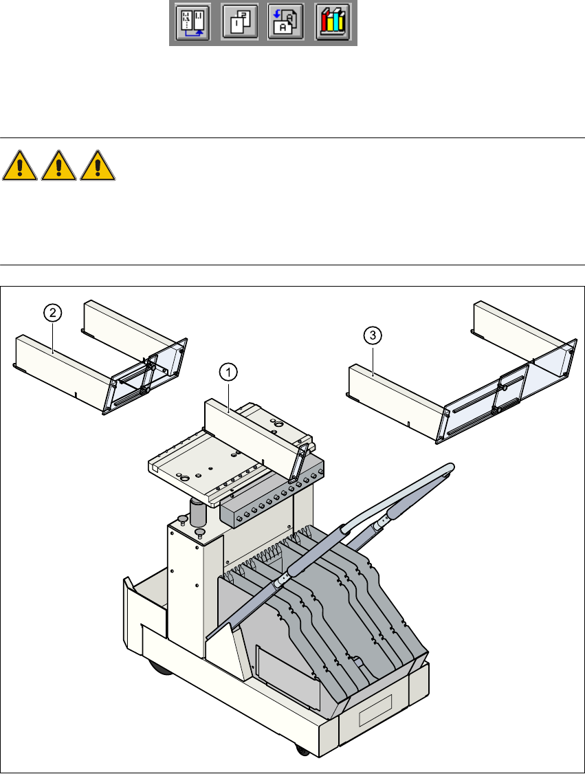
2.2.5 Guards on the component table locations
DANGER 2
All locations must be equipped with feeder modules in order to guarantee operational safety. If
there are not enough feeder modules available, a guard (dummy feeder) must be used in place
of the modules.
2
Fig. 2.2 - 8 Guards on the component table
(1) Guard for 1 location Item no. 00116820-01
(2) Guard for 6 - 10 locations Item no. 00116821-01
(3) Guard for 11 - 20 locations Item no. 00116822-01