00191369-02.pdf - 第77页
User Manual HS-50 2 Operational Safety Software Version S R.501.xx 12/99 Issue US 2.3 Residual voltages in the servo unit and discharge times 77 t I I t 2.3 Residual volt ages in the servo unit and discharge times If the…
2 Operational Safety User Manual HS-50
2.2 Safety equipment Software Version SR.501.xx 12/99 Issue US
76
t IIt
2.2.5 Guards on the component table locations
DANGER 2
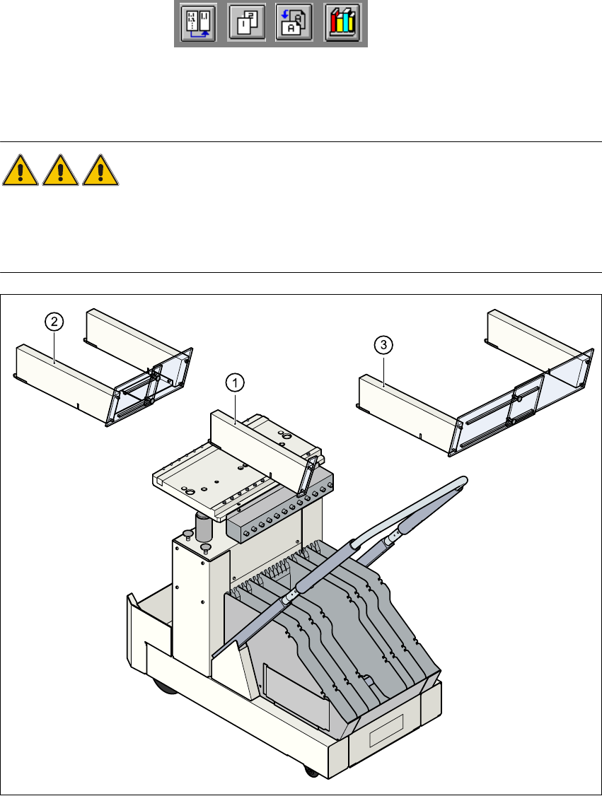
All locations must be equipped with feeder modules in order to guarantee operational safety. If
there are not enough feeder modules available, a guard (dummy feeder) must be used in place
of the modules.
2
Fig. 2.2 - 8 Guards on the component table
(1) Guard for 1 location Item no. 00116820-01
(2) Guard for 6 - 10 locations Item no. 00116821-01
(3) Guard for 11 - 20 locations Item no. 00116822-01
User Manual HS-50 2 Operational Safety
Software Version SR.501.xx 12/99 Issue US 2.3 Residual voltages in the servo unit and discharge times
77
t IIt
2.3 Residual voltages in the servo unit and discharge
times
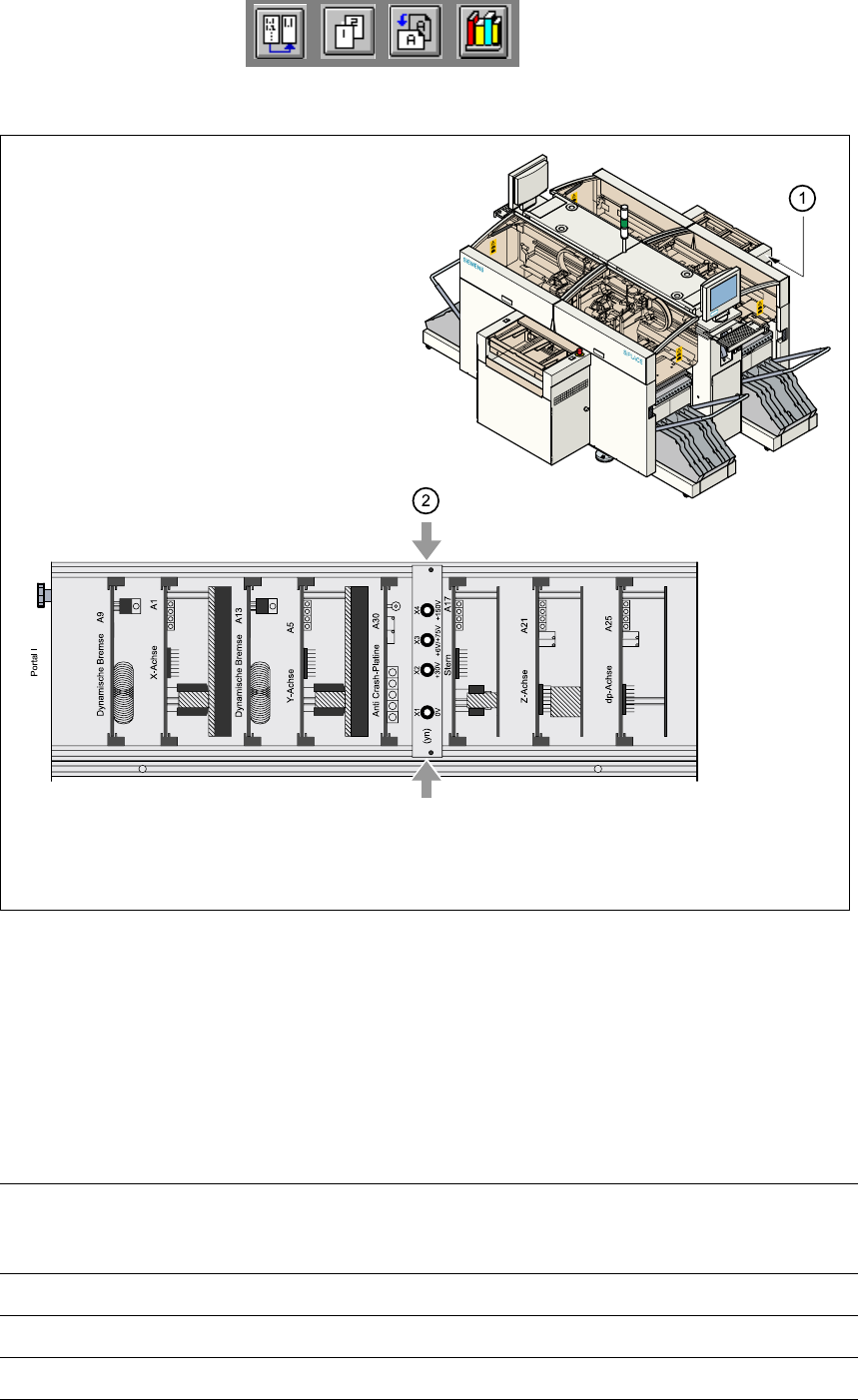
If the emergency stop mushroom-head push-button is pressed or the placement system is
switched off, the 200 V link voltage for the gantry axes and 100 V link voltage for the star axes are
discharged to harmless residual voltages in a very short time. 2
The voltages can be tapped at test sockets X1 - X4 on the voltage measuring unit in the servo unit.2
DANGER 2
The placement system is supplied with 3 x 204 V AC (US version), 3 x 230 V AC, 3 x 380 V AC,
3 x 400 V AC or 3 x 415 V AC ± 5 %, 50/60 Hz mains voltage. This means that some parts of the
system carry potentially lethal voltages - even when switched off at the main switch. Incorrect
handling of the placement system can therefore result in death or severe injury or considerable
damage to equipment.
Å Always follow the applicable accident prevention and DIN regulations (particularly DIN EN
60 204, part 1).
Å The cover over the servo unit must only be opened by qualified and trained personnel.
2
2 Operational Safety User Manual HS-50
2.3 Residual voltages in the servo unit and discharge times Software Version SR.501.xx 12/99 Issue US
78
t IIt
2
Fig. 2.3 - 1 Test sockets on the voltage measuring unit in the servo unit
(1) Position of the servo units
(2) Voltage measuring unit on the servo unit
2.3.1 Operating voltages, residual voltages and discharge times after
pressing the emergency stop mushroom-head push-button
Test sockets X2, X3,
X4 measured to X1
(GND)
Voltage in normal
mode
Residual voltage
during emergency
stop
Discharge times
X2 + 30 VDC + 30 VDC -
X3 + 100 VDC < 10 VDC 50 sec
X4 + 200 VDC < 10 VDC 7 sec