00191369-02.pdf - 第79页
User Manual HS-50 2 Operational Safety Software Vers ion SR.501.xx 12/99 Issue US 2.4 Disabling the compres sed air supply and releasing the pres sure 79 t I I t 2.3.2 Residual volt ages and discharge times af ter switch…
2 Operational Safety User Manual HS-50
2.3 Residual voltages in the servo unit and discharge times Software Version SR.501.xx 12/99 Issue US
78
t IIt
2
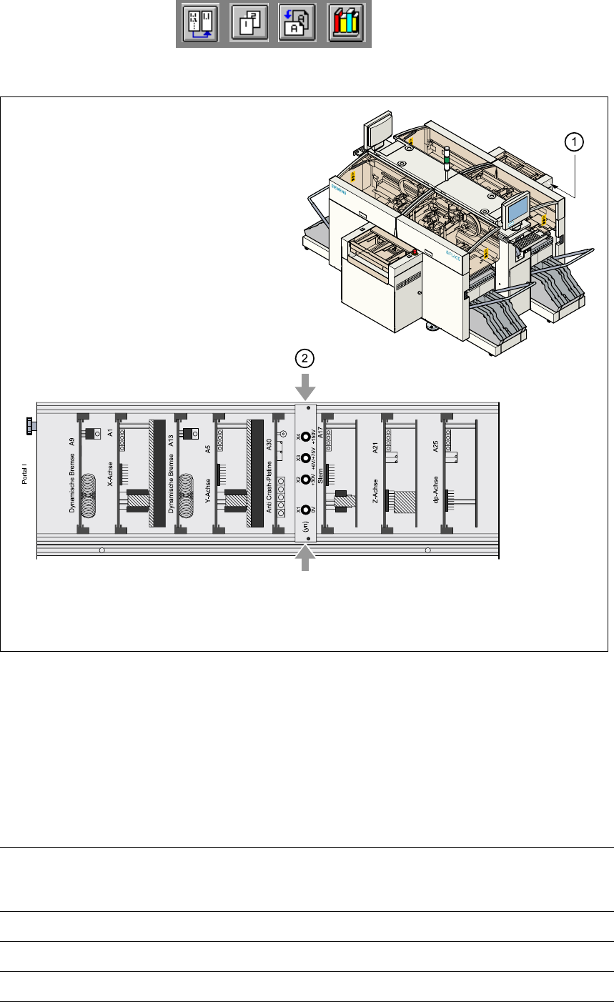
Fig. 2.3 - 1 Test sockets on the voltage measuring unit in the servo unit
(1) Position of the servo units
(2) Voltage measuring unit on the servo unit
2.3.1 Operating voltages, residual voltages and discharge times after
pressing the emergency stop mushroom-head push-button
Test sockets X2, X3,
X4 measured to X1
(GND)
Voltage in normal
mode
Residual voltage
during emergency
stop
Discharge times
X2 + 30 VDC + 30 VDC -
X3 + 100 VDC < 10 VDC 50 sec
X4 + 200 VDC < 10 VDC 7 sec
User Manual HS-50 2 Operational Safety
Software Version SR.501.xx 12/99 Issue US 2.4 Disabling the compressed air supply and releasing the pressure
79
t IIt
2.3.2 Residual voltages and discharge times after switching off at the main switch
2
CAUTION The following conditions must be fulfilled before switching off the placement
system (apart from in emergencies) in order to avoid the loss of data: 2
– the placement system must have stopped transmitting machine, set-up and cluster data.
– the placement system must have stopped processing the PCBs.
– the placement system must have completed the start-up phase.
2.4 Disabling the compressed air supply and releasing
the pressure
The compressed air operating pressure is permanently set to 5.5 bar. The position of the com-
pressed air unit is indicated by item 4 in Figure 2.4 - 1
. The compressed air supply to the place-
ment system may be interrupted using the shut-off valve (item 1 in Figure 2.4 - 1
the diagram). 2
Å Open the safety doors.
Å Turn the lever of the shut-off valve (item 1 in Figure 2.4 - 1) from the vertical to the horizontal
position.
Å Check the operating pressure gauge and the pressure gauge for the compressed air supply to
the stopper (items 2 and 3 in Figure 2.4 - 1
). When the placement system is switched on, the
pres-sure drops to 0 bar within 1 minute.
CAUTION When the machine is switched on, do not use the stop valve to interrupt the
compressed air supply for more than 30 minutes. If you need to shut off the pneumatic system for
longer in order to carry out maintenance or servicing work, you must switch the placement system
off at the main switch and disconnect it from the power supply. 2
Test sockets X2, X3, X4
measured to X1 (GND)
Residual voltage when main
switch is switched off
Discharge times
X2 < 10 VDC < 2 sec
X3 < 10 VDC < 50 sec
X4 < 10 VDC < 7 sec
2 Operational Safety User Manual HS-50
2.4 Disabling the compressed air supply and releasing the pressure Software Version SR.501.xx 12/99 Issue US
80
t IIt
2
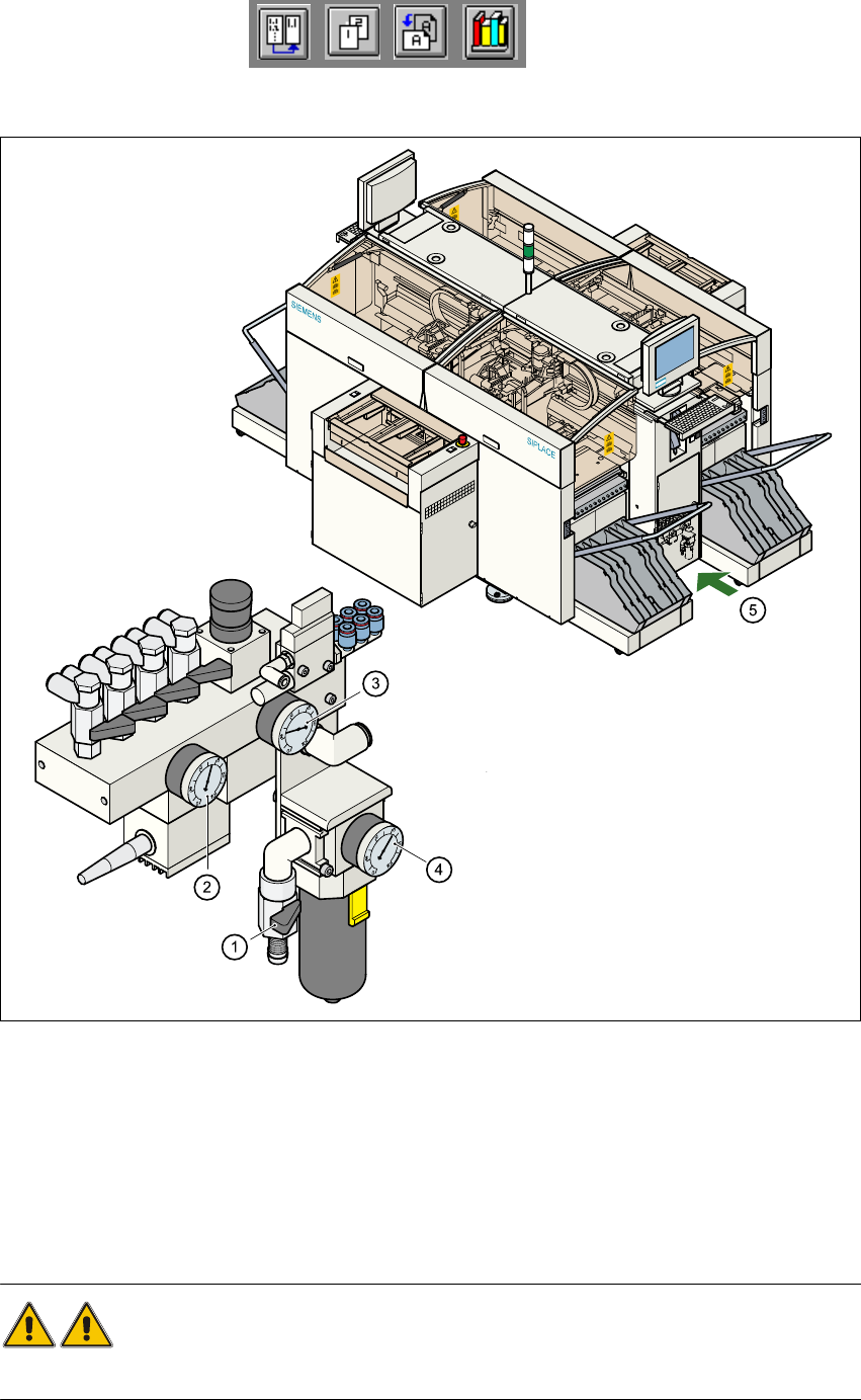
Fig. 2.4 - 1 Compressed air unit on the placement system
WARNING 2
NEVER detach compressed air lines while they are still pressurized. Risk of injury.
(1) Shut-off valve lever in the CLOSED position
(2) Operating pressure gauge
(3) Pressure gauge for the component table operating pressure
(4) Input pressure manometer
(5) Position of the compressed air unit on the placement system