00191369-02.pdf - 第82页
2 Operational Safety User Manual HS -50 2.5 Energy state of t he placement system after switching off at t he main switch Software Version SR.501.xx 12/99 Issue US 82 t I I t 2 Fig. 2.5 - 1 Position of the serv o unit, m…
User Manual HS-50 2 Operational Safety
Software Version SR.501.xx 12/99 Issue US 2.5 Energy state of the placement system after switching off at the main switch
81
t IIt
2.5 Energy state of the placement system after switch-
ing off at the main switch
DANGER 2
The placement system is supplied with 3 x 204 V AC (US version), 3 x 230 V AC, 3 x 380 V AC,
3 x 400 V AC or 3 x 415 V AC ± 5 %, 50/60 Hz mains voltage. This means that some parts of the
system carry potentially lethal voltages - even when switched off at the main switch. Incorrect
handling of the placement system can therefore result in death or severe injury or considerable
damage to equipment.
Å Always follow the applicable accident prevention and DIN regulations (particularly DIN 60 204,
part 1).
Å The cover over the servo unit must only be opened by qualified and trained personnel.
2 Operational Safety User Manual HS-50
2.5 Energy state of the placement system after switching off at the main switch Software Version SR.501.xx 12/99 Issue US
82
t IIt
2
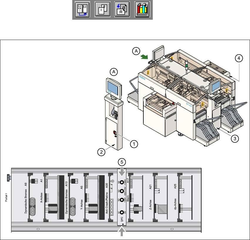
Fig. 2.5 - 1 Position of the servo unit, main switch, service socket and compressed air unit
on the placement system
2
(1) Main switch
(2) Service socket behind the safety doors
(3) Compressed air unit
(4) Servo unit
(5) Measuring unit in the servo unit
User Manual HS-50 2 Operational Safety
Software Version SR.501.xx 12/99 Issue US 2.5 Energy state of the placement system after switching off at the main switch
83
t IIt
2
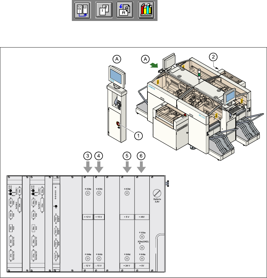
Fig. 2.5 - 2 Position of the control unit and main switch
(1) Main switch
(2) Control unit
(3) Power supply unit ± 12 VDC
(4) Power supply unit ± 15 VDC
(5) Power supply unit + 5 VDC/+ 24 VDC
(6) Power supply unit + 5 VDC/+ 50 VDC