00191369-02.pdf - 第84页
2 Operational Safety User Manual HS -50 2.5 Energy state of t he placement system after switching off at t he main switch Software Version SR.501.xx 12/99 Issue US 84 t I I t 2.5.1 Main switch switched off - machine syst…
User Manual HS-50 2 Operational Safety
Software Version SR.501.xx 12/99 Issue US 2.5 Energy state of the placement system after switching off at the main switch
83
t IIt
2
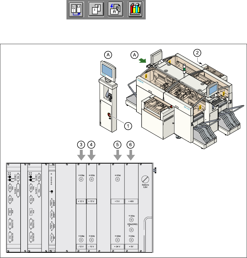
Fig. 2.5 - 2 Position of the control unit and main switch
(1) Main switch
(2) Control unit
(3) Power supply unit ± 12 VDC
(4) Power supply unit ± 15 VDC
(5) Power supply unit + 5 VDC/+ 24 VDC
(6) Power supply unit + 5 VDC/+ 50 VDC
2 Operational Safety User Manual HS-50
2.5 Energy state of the placement system after switching off at the main switch Software Version SR.501.xx 12/99 Issue US
84
t IIt
2.5.1 Main switch switched off - machine system connected to the
main power supply
The following table shows the voltages of the individual modules when the main switch is switched
off, but the placement system is still connected to the main power supply. 2
DANGER 2
The following components still carry potentially lethal voltages even if the main switch is switched
off: 2
– cable connection terminals 1, 3, and 5 of S1 main switch
– Z1 main power filter
– BU1 service socket
– F1 automatic circuit breaker for the service socket
– The color of all individual wires, which still carry potentially lethal voltages even if the main
switch is switched off is brown.
2
Module Voltage
Z1 main power filter
Cable connection terminals L1, L2, L3
[9$&
[9$&
[9$&
[9$&
[9$&
BU1 service socket
9$&
9$&
9$&
9$&
9$&
F1 automatic circuit breaker
9$&
9$&
9$&
9$&
9$&
User Manual HS-50 2 Operational Safety
Software Version SR.501.xx 12/99 Issue US 2.5 Energy state of the placement system after switching off at the main switch
85
t IIt
2
2.5.2 Main switch switched off - machine disconnected from the power supply
The placement system is de-energized, apart from slight residual voltages in the servo unit. 2
2
2.5.3 Compressed air conditions in the machine after switching off
at the main switch
When the placement system is switched off at the main switch (item 1 in Figure 2.5 - 1) or the
power supply to the placement system fails, the electrically-controlled main valve Y1 shuts off the
compressed air unit (item 3 in Figure 2.5 - 1
). The pressure drops to 0 bar within 5 seconds. 2
S1 main switch
Cable connection terminals 1, 3, 5
[9$&
[9$&
[9$&
[9$&
[9$&
Servo unit (see item 5 in Figure 2.5 - 2
)
Test socket X2
Test socket X3
Test socket X4
GND X1
< 10 VDC
< 10 VDC
< 10 VDC
Control unit (see items 3, 4, 5 and 6
in Figure 2.5 - 2
)
Test socket + 12 VDC (x3ta)
Test socket - 12 VDC (x4ta)
Test socket + 15 VDC (x3tb)
Test socket - 15 VDC (x4tb)
Test socket + 5 VDC (x3td)
Test socket + 24 VDC (x4td)
Test socket + 50 VDC (x5te)
Test socket + 5 VDC (x4te)
GND (x3td)
0 VDC
0 VDC
0 VDC
0 VDC
0 VDC
0 VDC
0 VDC
0 VDC