00191369-02.pdf - 第86页
2 Operational Safety User Manual HS -50 2.6 Lock out and tag ou t procedure Software Version SR.501.xx 12 /99 Issue US 86 t I I t 2.6 Lock out and t ag o ut procedure 2.6.1 Purpose and scope Before pe rformi ng any mai n…
User Manual HS-50 2 Operational Safety
Software Version SR.501.xx 12/99 Issue US 2.5 Energy state of the placement system after switching off at the main switch
85
t IIt
2
2.5.2 Main switch switched off - machine disconnected from the power supply
The placement system is de-energized, apart from slight residual voltages in the servo unit. 2
2
2.5.3 Compressed air conditions in the machine after switching off
at the main switch
When the placement system is switched off at the main switch (item 1 in Figure 2.5 - 1) or the
power supply to the placement system fails, the electrically-controlled main valve Y1 shuts off the
compressed air unit (item 3 in Figure 2.5 - 1
). The pressure drops to 0 bar within 5 seconds. 2
S1 main switch
Cable connection terminals 1, 3, 5
[9$&
[9$&
[9$&
[9$&
[9$&
Servo unit (see item 5 in Figure 2.5 - 2
)
Test socket X2
Test socket X3
Test socket X4
GND X1
< 10 VDC
< 10 VDC
< 10 VDC
Control unit (see items 3, 4, 5 and 6
in Figure 2.5 - 2
)
Test socket + 12 VDC (x3ta)
Test socket - 12 VDC (x4ta)
Test socket + 15 VDC (x3tb)
Test socket - 15 VDC (x4tb)
Test socket + 5 VDC (x3td)
Test socket + 24 VDC (x4td)
Test socket + 50 VDC (x5te)
Test socket + 5 VDC (x4te)
GND (x3td)
0 VDC
0 VDC
0 VDC
0 VDC
0 VDC
0 VDC
0 VDC
0 VDC

2 Operational Safety User Manual HS-50
2.6 Lock out and tag out procedure Software Version SR.501.xx 12/99 Issue US
86
t IIt
2.6 Lock out and tag out procedure
2.6.1 Purpose and scope
Before performing any maintenance work or service work, a procedure of locking and tagging
must be followed. The procedure, when followed correctly eliminates the possibility of an em-
ployee being injured. 2
NOTE 2
These procedures represent the minimum lock/tag out requirements. Any additional safe-guards
needed to complete work safely can be specified by facilities supervision, the safety officer, the
safety committee and the health department.
2
2.6.2 Description
Whenever it becomes necessary to isolate, control and release energy, the following procedure is
to be followed 2
(1) Notify affected employees.
(2) Shut down equipment, using normal stopping procedures, such as
– depressing the stop button
– shutting down the station computer or
– switching off the placement system at the main switch.
(3) Isolate the equipment from all its energy sources such as
– compressed air supply and
– power supply.
(4) Lock Out equipment.
– Apply the lock and the lockout whenever possible.
2
User Manual HS-50 2 Operational Safety
Software Version SR.501.xx 12/99 Issue US 2.6 Lock out and tag out procedure
87
t IIt
2
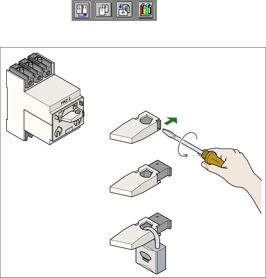
Fig. 2.6 - 1 Locking the motor contactor
(1) Turn the operating lever (1) counter-clockwise.
(2) Use the screwdriver to push the locking lug (2) out of the operating lever (1).
(3) Secure the operating lever with a padlock (3).
2
– The Tag Out alternative:
If a machine can be locked out, it must be. However, there are situations where energy iso-
lating devices can not accommodate locks. In these cases, the energy isolating devices must
be tagged to warn employees that the machine is de-energized for servicing. The tag must be
securely fastened, it must be placed in a position visible to all and it may only be removed by
the person who attached it. 2