00191369-02.pdf - 第95页
User Manual HS-50 3 Introduction and Basic Concepts Software Vers ion SR.501.xx 12/99 Issue US 3.1 Mac hine Displays a nd Controls 95 t I I t 3.1.1.1 General Every statio n is e quipped wi th a " station comp uter&q…
3 Introduction and Basic Concepts User Manual HS-50
3.1 Machine Displays and Controls Software Version SR.501.xx 12/99 Issue US
94
t IIt
3.1 Machine Displays and Controls
3.1.1 Overview
3
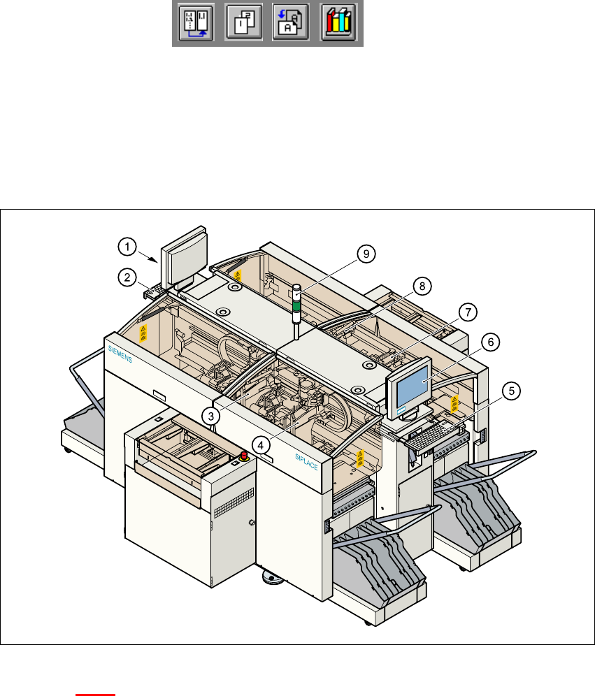
Fig. 3.1 - 1 Overview
Key to Fig. 3.1 - 1
(1) Monitor (left side)
(2) Keyboard (left side)
(3) Gantry 4
(4) Gantry 1
(5) Keyboard (right side)
(6) Monitor (right side)
(7) Gantry 2
(8) Gantry 3
(9) Fault indicator lamp
User Manual HS-50 3 Introduction and Basic Concepts
Software Version SR.501.xx 12/99 Issue US 3.1 Machine Displays and Controls
95
t IIt
3.1.1.1 General
Every station is equipped with a "station computer". The station computer is located on the side
of the input area behind a machine base door. This area also accommodates the uninterruptible
power supply (UPS).
A monitor with touch screen and sliding keyboard with integrated trackball is mounted on either
side of the station (see Figure 3.1 - 1
).
NOTE
You can operate the SR software interface either via the keyboard and trackball or via the touch
screen (see section 3.2.1). 3
The position of the switches and buttons (main switch, key-operated switches, start/stop button,
EMERGENCY STOP button etc.) is illustrated in Figure 3.1 - 3
. The functions are described in
Chapter 2
.
3
WARNING
The machine base doors may only be opened by qualified personnel since certain machine com-
ponents carry hazardous voltages.
The relevant accident prevention and applicable regulations regarding electrical/electromechani-
cal installations must be strictly complied with. Failure to do so may result in death, severe phys-
ical injury or considerable damage to property. 3
3
3
3 Introduction and Basic Concepts User Manual HS-50
3.1 Machine Displays and Controls Software Version SR.501.xx 12/99 Issue US
96
t IIt
3.1.1.2 Machine Areas
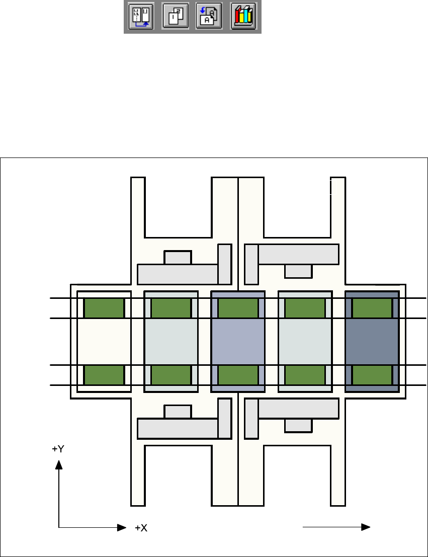
The figure below provides a diagrammatic overview of the individual areas of a
SIPLACE HS-50 placement station.
The terms used in the figure to describe these areas are also used in the texts in the user interface
and in the User’s Manual. 3
Fig. 3.1 - 2 Machine areas
Explanation of Terms:
PA = processing area (1 or 2) 3
3
The conveyor is subdivided into the following sections in accordance with the machine areas:3
Input conveyor => Processing conveyor 1 => Intermediate conveyor => Processing conveyor
2 => Output conveyor 3
Direction of transport
Input area
Location 3
Location 1
Location 2
Gantry 4
Gantry 3
Gantry 2
Gantry 1
Conveyor 2
(left)
Conveyor 1
(right)
Location 4
PA1
Intermediate
conveyor
PA2
Output
conveyor