00191369-02.pdf - 第97页
User Manual HS-50 3 Introduction and Basic Concepts Software Vers ion SR.501.xx 12/99 Issue US 3.1 Mac hine Displays a nd Controls 97 t I I t 3.1.2 Machine Switches and Buttons The figure below presents the po sitio n of…
3 Introduction and Basic Concepts User Manual HS-50
3.1 Machine Displays and Controls Software Version SR.501.xx 12/99 Issue US
96
t IIt
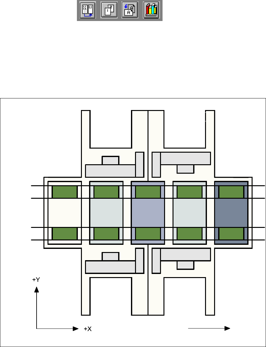
3.1.1.2 Machine Areas
The figure below provides a diagrammatic overview of the individual areas of a
SIPLACE HS-50 placement station.
The terms used in the figure to describe these areas are also used in the texts in the user interface
and in the User’s Manual. 3
Fig. 3.1 - 2 Machine areas
Explanation of Terms:
PA = processing area (1 or 2) 3
3
The conveyor is subdivided into the following sections in accordance with the machine areas:3
Input conveyor => Processing conveyor 1 => Intermediate conveyor => Processing conveyor
2 => Output conveyor 3
Direction of transport
Input area
Location 3
Location 1
Location 2
Gantry 4
Gantry 3
Gantry 2
Gantry 1
Conveyor 2
(left)
Conveyor 1
(right)
Location 4
PA1
Intermediate
conveyor
PA2
Output
conveyor
User Manual HS-50 3 Introduction and Basic Concepts
Software Version SR.501.xx 12/99 Issue US 3.1 Machine Displays and Controls
97
t IIt
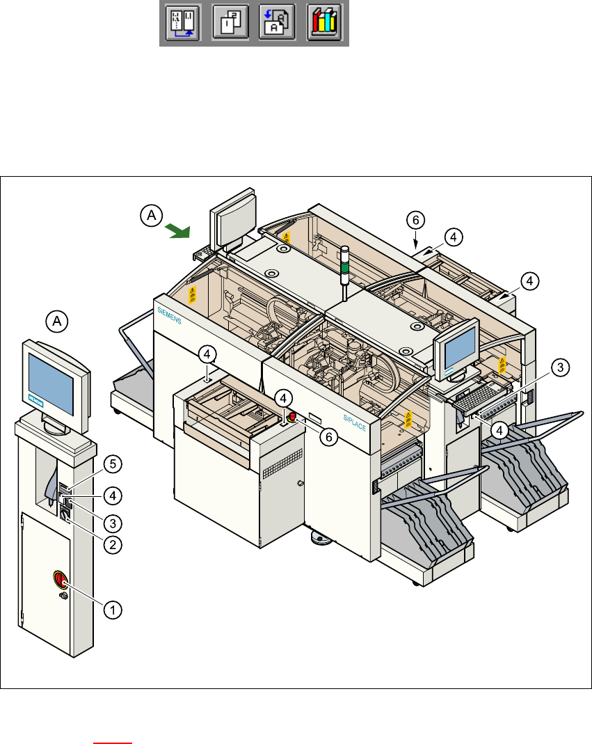
3.1.2 Machine Switches and Buttons
The figure below presents the position of the switches and buttons on the machine. 3
3
Fig. 3.1 - 3 Position of switches and buttons on the machine
Key to Figure 3.1 - 3
A View of operating panel, left side 3
(1) Main switch
(2) Key-operated switch
(3) Stop button (black)
(4) Start button (white)
(5) Component counter
(6) EMERGENCY STOP button
3 Introduction and Basic Concepts User Manual HS-50
3.1 Machine Displays and Controls Software Version SR.501.xx 12/99 Issue US
98
t IIt
WARNING
Only appropriately qualified personnel are permitted to use the key-operated switch for service or
maintenance work. The key must be removed to prevent unauthorized access as otherwise seri-
ous injury to personnel or damage to the machine may occur. 3
3
3.1.3 Main Fault Indicator
The main fault indicator (see Figure 3.1 - 1) contains 2 fault indicator lights (white) together with
an operating indicator light (green)
The operating indicator light is located between the two fault indicator lights. This indicates
whether the machine is in production or wait mode.
The nature and location of any malfunction can be identified using the operating indicator light
(flashing, glowing etc.) and the two fault indicator lights.
The following section describes the information provided by the two fault indicator lights.
NOTE
The operating statuses (or their meanings) of the two fault indicator lights can be individually pro-
grammed to respond to local circumstances (see the description of the "Programmable Operating
Statuses" in the next section). 3
3
3
3