00191369-02.pdf - 第98页
3 Introduction and Basic Concepts User Manual HS-50 3.1 Machine Displays and Controls Software Version SR.501.xx 12/99 Issue U S 98 t I I t W ARNING Only appr opriate ly qual ified personne l are perm itted to us e the k…
User Manual HS-50 3 Introduction and Basic Concepts
Software Version SR.501.xx 12/99 Issue US 3.1 Machine Displays and Controls
97
t IIt
3.1.2 Machine Switches and Buttons
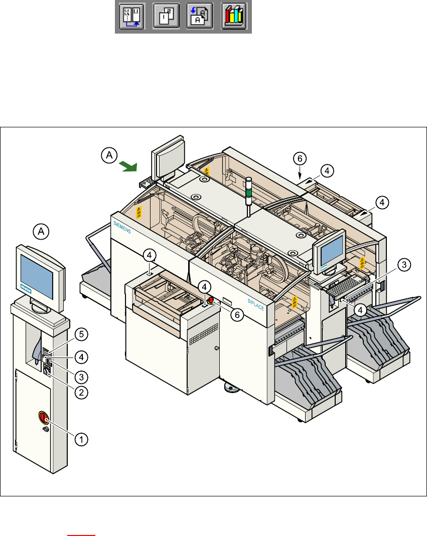
The figure below presents the position of the switches and buttons on the machine. 3
3
Fig. 3.1 - 3 Position of switches and buttons on the machine
Key to Figure 3.1 - 3
A View of operating panel, left side 3
(1) Main switch
(2) Key-operated switch
(3) Stop button (black)
(4) Start button (white)
(5) Component counter
(6) EMERGENCY STOP button
3 Introduction and Basic Concepts User Manual HS-50
3.1 Machine Displays and Controls Software Version SR.501.xx 12/99 Issue US
98
t IIt
WARNING
Only appropriately qualified personnel are permitted to use the key-operated switch for service or
maintenance work. The key must be removed to prevent unauthorized access as otherwise seri-
ous injury to personnel or damage to the machine may occur. 3
3
3.1.3 Main Fault Indicator
The main fault indicator (see Figure 3.1 - 1) contains 2 fault indicator lights (white) together with
an operating indicator light (green)
The operating indicator light is located between the two fault indicator lights. This indicates
whether the machine is in production or wait mode.
The nature and location of any malfunction can be identified using the operating indicator light
(flashing, glowing etc.) and the two fault indicator lights.
The following section describes the information provided by the two fault indicator lights.
NOTE
The operating statuses (or their meanings) of the two fault indicator lights can be individually pro-
grammed to respond to local circumstances (see the description of the "Programmable Operating
Statuses" in the next section). 3
3
3
3

User Manual HS-50 3 Introduction and Basic Concepts
Software Version SR.501.xx 12/99 Issue US 3.1 Machine Displays and Controls
99
t IIt
3.1.3.1 Functions
General Operating Statuses: 3
– Operating indicator light continuously illuminated
The machine is operating.
– Operating indicator light flashes
The machine is waiting for a PCB in the input conveyor or is waiting for the output conveyor to
become free.
– Fault light flashes
One or more tracks are empty at the feeder location of the gantry in question.
However, the machine will process any components present.
– Fault light continuously illuminated
An error has occured at the gantry in question--> the machine has stopped.
– Both lights continuously illuminated
An error has occurred which affects the entire machine--> the machine has stopped.
3
Programmable Operating Statuses: 3
Table 3.1 - 1 shows the operating states which have been programmed in the standard configuration
(version as delivered) together with the meaning these states have with regard to the main fault in-
dicator. 3
NOTE 3
The entries in the table next to "flashes" refer to the frequency with which the relevant lamp flashes
for a given event.
The entry (1, 5), for example, can be explained as follows: 3
– The first number in the brackets indicates the time, expressed in 100 msec intervals, for which
the fault indicator lamp is switched on, i.e. 1 x 100 msec in the above example.
– The second number in the brackets indicates the time, expressed in 100 msec intervals, for
which the fault indicator lamp is switched off, i.e. 5 x 100 msec in the above example.
NOTE
The file containing the parameters for configuring the main fault indicator is located in the directory
containing the machine files on the station computer. Changes to the parameters in this file must
be made by suitably qualified staff only. 3