SA_HF_intern_0194307-02_eng - 第45页
SIPL ACE HF-Ser ies Replacing the X -Drive (Prima ry) [00375245 -xx] Serv ice Gan tri es 3 Copy ri ght © 200 4 S ie m ens 0019 43 07- 02 Is su e 1 1/ 2004 3-31 Check the dista nce betw een th e X-drive and t he magn et…
3
Service
Gantries
SIPLACE HF-Series
Replacing the X-Drive (Primary) [00375245-xx]
3-30
00194307-02 Issue 11/2004 Copyright © 2004 Siemens
Installation
1
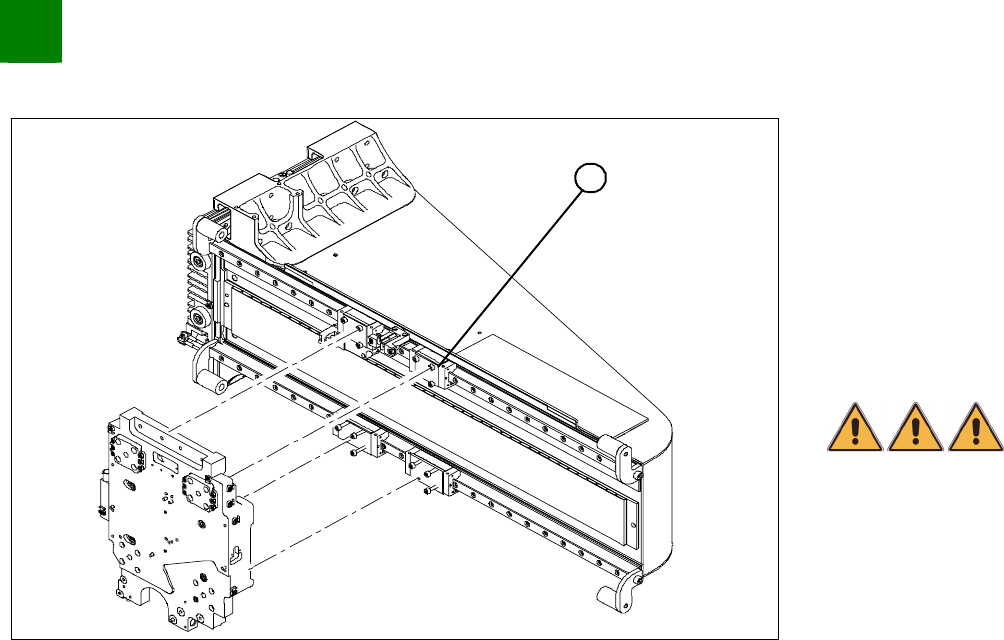
Clean the contact surface of the guide slide (1) with a dressing
stone (oil stone). Then wipe the surface clean with ethanol.
Fully tighten the forcing screws on each side of the new X-drive.
Place the foam mat on the magnetic strip.
Lift the new X-drive at the guide slide and secure the drive with
the M4x60 locking screws.
Pull out the foam mat.
DANGER
Risk of fatal injuries through trapping limbs. Do not place body
members between the X-drive and the magnetic strip.
Alternately loosen the forcing screws so that they are
unscrewed evenly. The X- drive must be evenly attracted
towards the magnet on all 4 sides. While doing this, press the
X-drive downwards onto the guide slides.
Install 3 fastening screws on each side. Take care to use the
right screw lengths.
Remove the locking screws and replace with the remaining
fastening screws.
Tighten all fastening screws crosswise with a torque wrench
(2.9 N).
Install the PCB camera.

SIPLACE HF-Series
Replacing the X-Drive (Primary) [00375245-xx]
Service
Gantries
3
Copyright © 2004 Siemens 00194307-02 Issue 11/2004 3-31
Check the distance between the X-drive and the magnet cover
with a 0.4 mm thickness gauge (plastic).
To do this, place the thickness gauge between the X-drive and
the magnet cover and then push the X-drive back and forth,
along the entire length - movement should be smooth with no
sticking or jamming.
3
Service
Gantries
SIPLACE HF-Series
Replacing the X-Drive (Primary) [00375245-xx]
3-32
00194307-02 Issue 11/2004 Copyright © 2004 Siemens
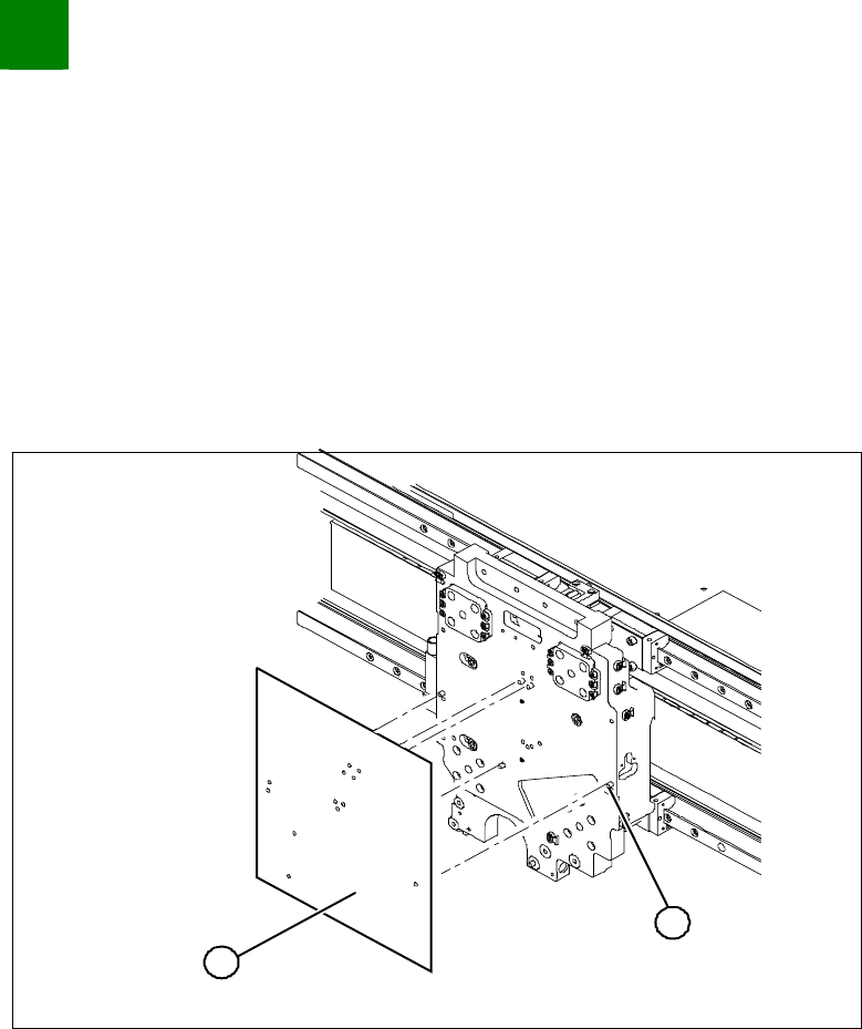
Sealing Drill Holes Where Necessary
Depending on the head configuration, different holes are used to fasten the head. Those not required must be sealed.
This prevents cooling air from escaping!!
Template for 12/6 C+P head (03011690-xx)
Template for twin head (03011693-xx)
Grub screws M 4x6-ST (00309422-xx)
1
2
Clean all holes with a pipecleaner and ethanol, to remove
residual adhesive.
Place the respective template on the centering pins of the head
mount and attach it.
Screw the grub screws through the holes on the template
(secure with Loctite 241) into the head mount.
The grub screws must be level with the surface of the head
mount or, better still, slightly sunk.