SA_HF_intern_0194307-02_eng - 第50页
3 Serv ice Gan tri es SIPL ACE HF-Ser ies Replacing the X -axis Read Head [ 03 006472] 3-36 0019 43 07- 02 Is su e 1 1/ 2004 Copy ri gh t © 2 004 S ie m ens Disassemb ly 4 3 1 2 1. Head mou nt - front vi ew 2. Read head …
SIPLACE HF-Series
Replacing the X-axis Read Head [03006472]
Service
Gantries
3
Copyright © 2004 Siemens 00194307-02 Issue 11/2004 3-35
5
1
3
2
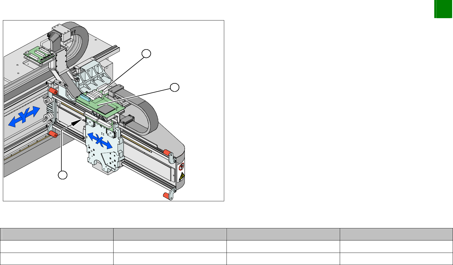
1. Vision board
2. Head interface (under the Vision board)
3. Read head position
Unplug the read head plug-and-socket connection from the
head interface (2).
Plug-and-socket connections
Assembly Gantry Board Terminal
X-axis read head Gantry 1 (DLM head) Head interface 03000901 X15ac
X-axis read head Gantry 2 (Twin head) Head interface 03000901 X15bc
3
Service
Gantries
SIPLACE HF-Series
Replacing the X-axis Read Head [03006472]
3-36
00194307-02 Issue 11/2004 Copyright © 2004 Siemens
Disassembly
4
3
1
2
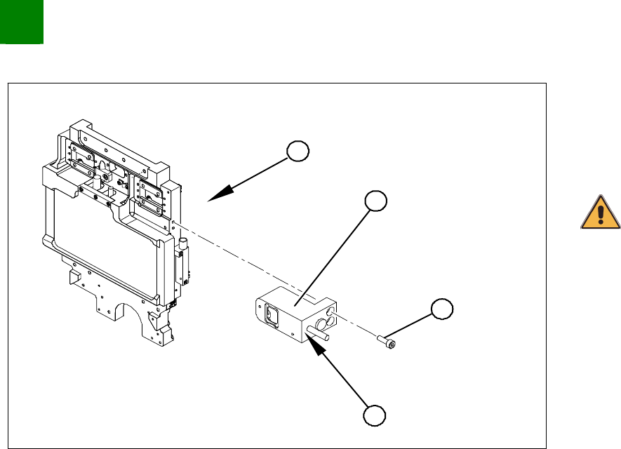
1. Head mount - front view
2. Read head
3. Fastening screws
4. Grub screws for fastening
CAUTION
Do not loosen or unscrew the grub screw (4).
Unthread the connection cable as far as the read head (2).
Undo the three screws (3) fastening the X-axis read head (2)
and carefully lift off the read head.
SIPLACE HF-Series
Replacing the X-axis Read Head [03006472]
Service
Gantries
3
Copyright © 2004 Siemens 00194307-02 Issue 11/2004 3-37
Installation
4
3
1
2
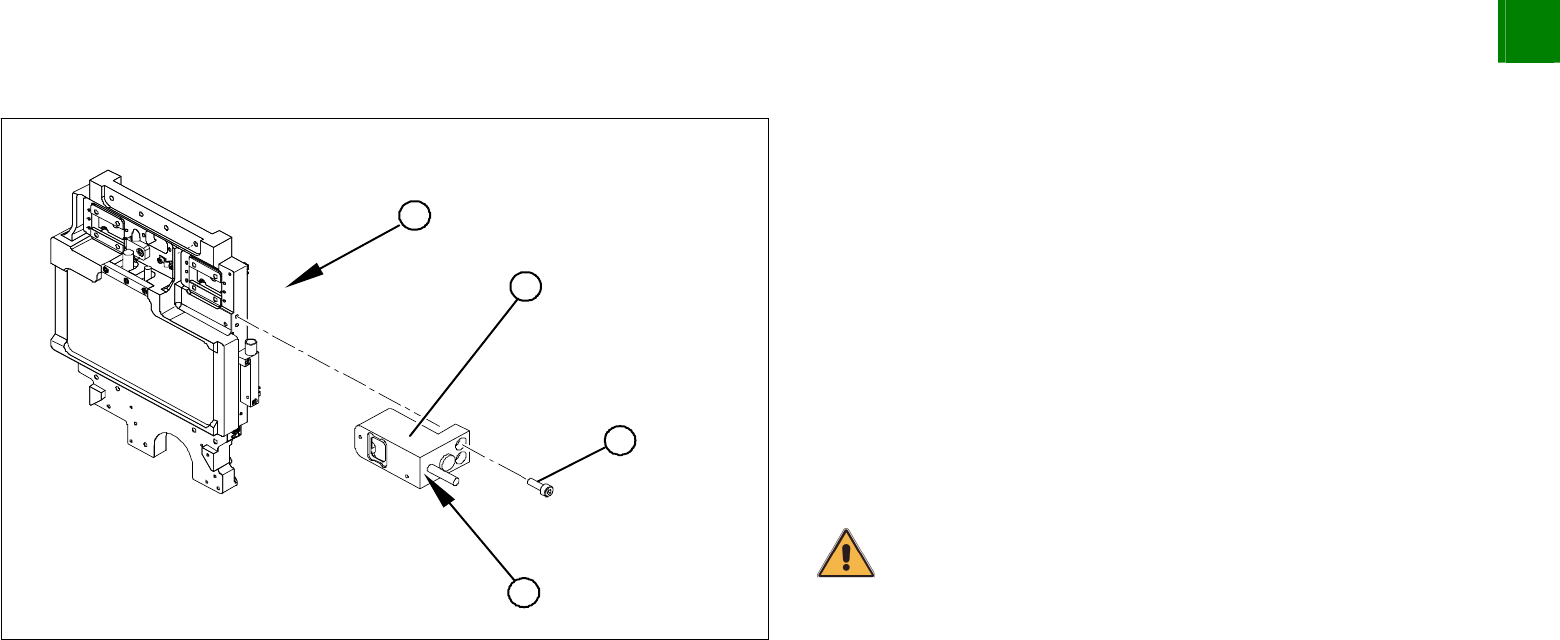
1. Head mount - front view
Clean the reading surface of the read head with a cloth and
ethanol or with a Q-tip.
Loosely fasten the read head (2) with three screws (3).
The read head must be aligned with a 0.4 mm gap to the scale.
Use the corresponding thickness gauge (plastic).
Tighten the fastening screws.
Reconnect to the electricity supply.
Make sure that the cables do not rub against anything. Fasten
them with cable ties.
CAUTION
Make sure that the axes can be moved without damaging the cables.
Check the track signals with an oscillograph.