SA_HF_intern_0194307-02_eng - 第70页
3 Serv ice Modular PCB Convey or System SIPL ACE HF-Ser ies Replacing the T oot hed Bel t f o r the Wid t h Adjust ment System Driv e [00369 662-xx] 3-56 0019 43 07- 02 Is su e 1 1/ 2004 Copy ri gh t © 2 004 S ie m ens 1…
SIPLACE HF-Series
Replacing the Toothed Belt for the Width Adjustment System Drive [00369662-xx]
Service
Modular PCB Conveyor System
3
Copyright © 2004 Siemens 00194307-02 Issue 11/2004 3-55
4
1
3
2
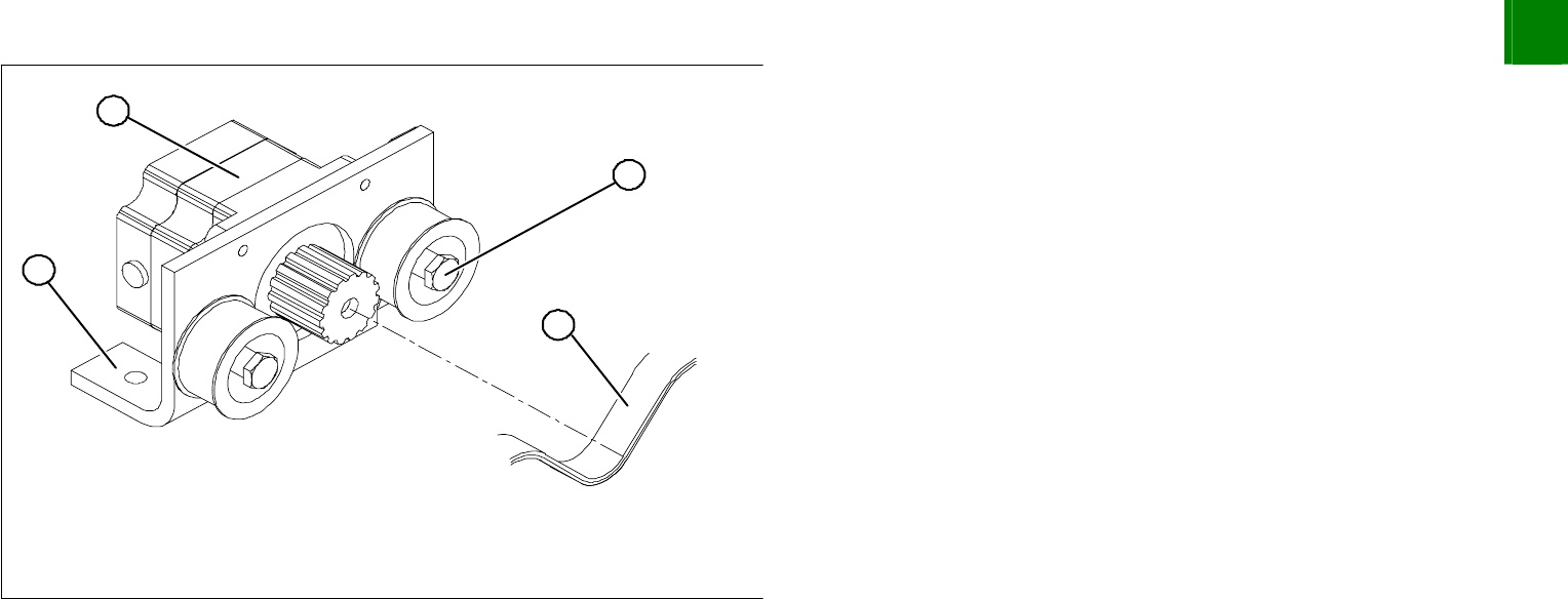
Loosen the excenter axis (1) on the deflection pulley and relax
the drive toothed belt (2).
Undo the screws fastening the mount (3) and remove the
stepping motor (4). This will enable you to thread the drive
toothed belt in more easily.
3
Service
Modular PCB Conveyor System
SIPLACE HF-Series
Replacing the Toothed Belt for the Width Adjustment System Drive [00369662-xx]
3-56
00194307-02 Issue 11/2004 Copyright © 2004 Siemens
1
1
5
4
3
2
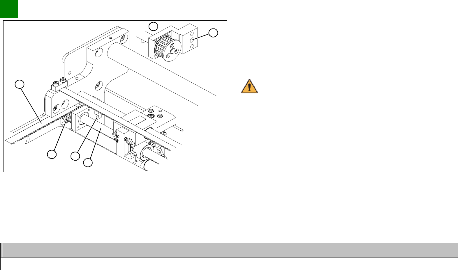
Remove the screw (1) fastening the ball screw and flange to the
base.
(Pos. 5 shows a rear view)
Remove the spindle (2) from its hole; the drive toothed belt (3)
can now be run out over the toothed wheels (4).
CAUTION
Make sure that the screw clamps are firmly attached.
Remove the complete drive toothed belt from the machine.
Thread the new toothed belt into the machine and run it over
the toothed wheels.
Install the flange and ball screw.
Run the drive toothed belt over the stepping motor deflection
pulley and install the stepping motor.
Tension the drive toothed belt.
Position the measuring point of the belt tension device at the
strand center of placement area 1 of the drive toothed belt.
Set the tension of the drive toothed belt according to the
following values.
Belt tension- width adjustment system
Drive toothed belt 30 Hz +/- 2 Hz
SIPLACE HF-Series
Replacing the Toothed Belt for the Width Adjustment System Drive [00369662-xx]
Service
Modular PCB Conveyor System
3
Copyright © 2004 Siemens 00194307-02 Issue 11/2004 3-57
3.3.1.1 Resetting the Parallelism of the Adjustment Unit
If a ball screw and adjustment unit have twisted out of position (the conveyor system will no longer run parallel), please
proceed as follows:
1
1
2
4
3
2
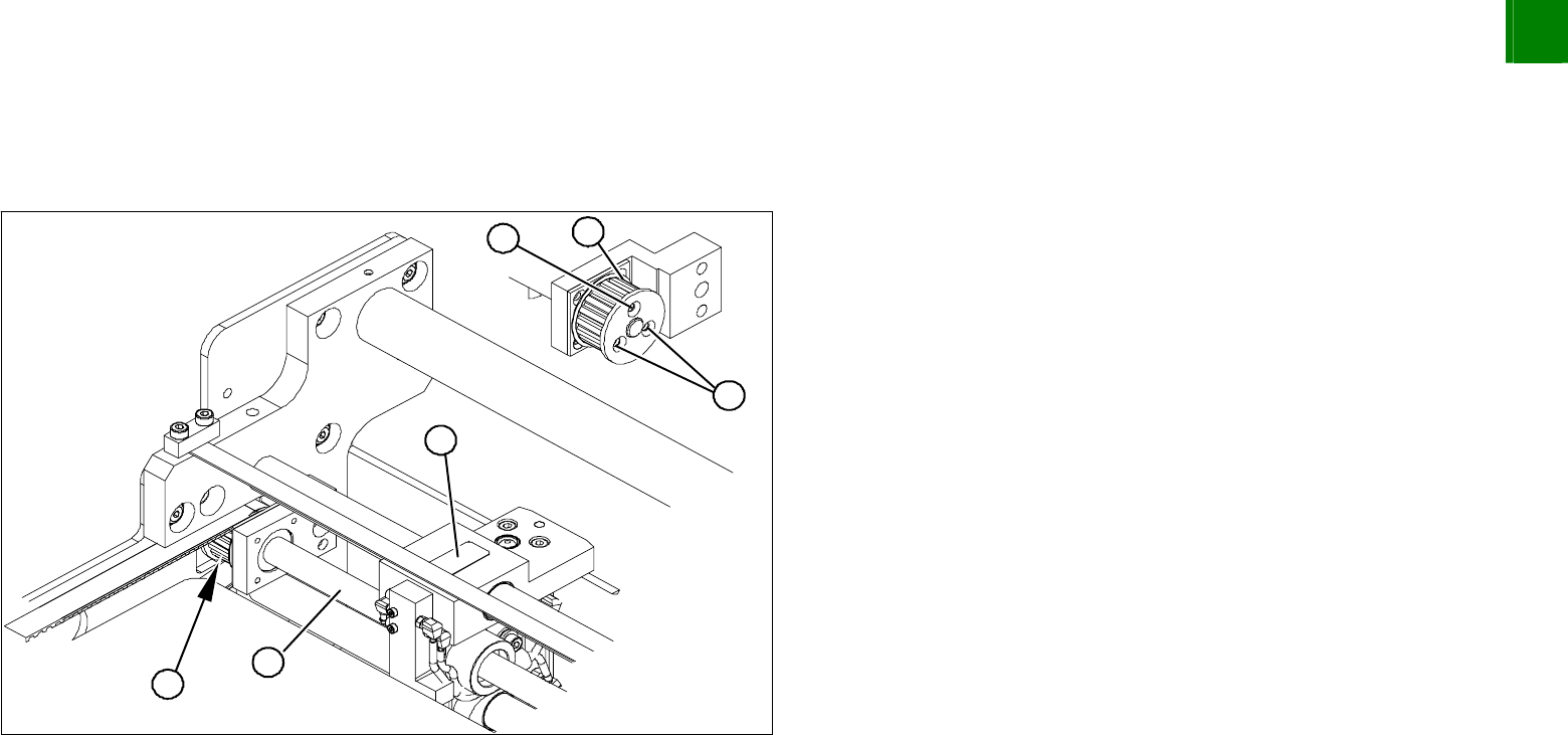
Unscrew the three fastening screws (2) on the toothed wheel
(1).
The ball screw (3) and adjustment unit (4) can now be manually
turned (hold onto the toothed wheel and revolve the ball screw).
Measure the distance between a fixed adjustment unit and the
fixed conveyor side.
Turn the loose ball screw (3) until the adjustment unit (4) is set
to this value.
Fix the position with the 3 fastening screws (2) on the toothed
wheel (1).